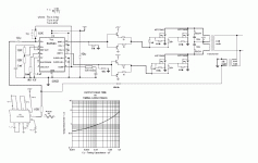
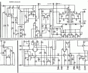
It does work quite well, and can even be used with an old style, superposed windings transformer.
The only types that are completely ruled out are toroidals.
Hello
Yes, I can even use one of my big standard EI silicon steel transformer, but it would better to bring down my SG3524 oscillation frequency to 200 hz or
300 hz, because at higher oscillation frequency the Eddy current would be quite high in my output transformer.
At those low oscillation frequency the LC low pass filter would need a big L coil, but it would be easyer to keep my SG3524 circuit very stable.
Thank
Bye
Gaetan
Last edited:
You shouldn't do that: at such low frequencies, the transformer will still be relatively "perfect", and the leakage will not be able to play its role.Hello
Yes, I can even use one of my big standard EI silicon steel transformer, but it would better to bring down my SG3524 oscillation frequency to 200 hz or
300 hz, because at higher oscillation frequency the Eddy current would be quite high in my output transformer.
This will generate high peak current and huge residues in the output.
You do not have to care about eddy current losses: what counts is the flux excursion, translated into volt/turn, and this remains constant.
When you increase the frequency without changing anything else, the peak induction decreases in a proportional manner.
The situation for hysteresis losses is different, because energy is lost for each cycle, but in practice, this is more or less compensated by the reduced induction level.
The only loss that does increase is caused by magnetic viscosity, but it remains relatively marginal.
In summary, if you operate the transformer at ~20KHz, you will incur some additional losses compared to 50/60Hz, but that will remain moderate and just requires a small derating.
Usu NE555
use 555 timer. But use it wisely. That will lessen the pains of calculations with discrete component designs. Yes, you will have to take some pains. I am choosing 555 as it is easily available everywhere.
Hello
Another way to do a NFB could be using a small transformer at the output like in my new schematic.
I've also done few littles others modifications.
Thank
Bye
Gaetan
use 555 timer. But use it wisely. That will lessen the pains of calculations with discrete component designs. Yes, you will have to take some pains. I am choosing 555 as it is easily available everywhere.
- Status
- This old topic is closed. If you want to reopen this topic, contact a moderator using the "Report Post" button.

