Concilate? I think you mean oscillate?
Your low-frequency instability suggests "motor-boating", which is a type of instability probably within whatever amplifier you're using, or one of your regulators is severely misbehaving.
http://cache.national.com/ds/LM/LM117.pdf
Follow the instructions on the data sheet on page 8 and 9. Excessive capacitance on the output is probably not very helpful; 10 uF - 100 uF
on the adjust pins of the regulators are helpful and larger amounts will not have much useful effect.
Large amounts of capacitance on the output of the Jung regulators are unnecessary; the design already has a very low output impedance at all audio frequencies--when constructed properly! Read the application notes very carefully and follow them to the letter. This is a very sophisticated and optimized design; I had to study the notes for quite a while to comprehend them and properly implement them in my applications.
The purpose of adding capacitance at the regulator output is to lower the output impedance but the super regulator has already extremely low output impedance, like microohms. Therefore adding something with milliohms seems rather pointless. The super regulator creates in an artifical way an extremly "large" capacitor. My advice is to have 100-470 uF max at the output, preferrable down towards 100 uF.
HiFiNutNut said:Actually the reason I want to try the Jung regulator is because I am a bit worried about my LM317/LM337 regulator. I followed the data sheet closely to design it and it has been working mostly very well for over 2 years. I am not too worried about the noise or the impedance because obviously the +-15V regulator gives pretty high-end sound.
The only issue is with possible conciliations. I found having low capacitance after the LM317/LM337 (less than 500uF) does not sound good. Adding a Rubycon ZL 2,200uF sounds very good. Of course, for each opamp, I use 125uF per rail, bypassed by 0.01uF film, and a 0.1uF film cross the rails. This sounds the best for me. Noise or impedance is not an issue.
But in a few occasions, which I can not replicate because it is intermittent, I saw my 12" woofers moving in and out at maximum excursion slower with no signals! I reckoned it was some resonance at only a few Hz. Where did they come from, I guess they may come from the low impedance large caps after the LM317/LM337. Because of the low impedance and low ESR, the resonance can not be damped sufficiently.
But would I get the same problem with the Jung regulator? I mean if I add large capacitance after the Jung regulator, would it conciliate at some points? You may say no capacitance is needed after the Jung regulator. Would it sound good in that case? Would it be able to deliver the transient at demands without the capacitor?
Has anyone done any critical A/B test between the sound of a Jung regulator and a very well implemented LM317/LM337 regulator with large caps?
Regards,
Bill
Hi Bill,
Having worked with Walt Jung on his super reg project, let me give you my take on this.
First of all, your slow moving woofers are not caused by any power supply issues. There is no 'direct' connection from the supply to the woofers. Even if the supply would slowly vary, still the amp controls the speaker. What you might have witnessed is a very low freq amp oscillation which in the old tube days we called 'motorboating'because of the sound it made. I have no idea how that happened in your amp, possibly you have ground loop issues.
To the regs: The 317/337 regs are among the best of the integrated regs, but are no match to a well designed discrete reg like Walts. Now I base this on measurements and how well the circuit emulates an 'indeal' voltage source. Whether there is an audible difference in practise depends on a lot of other things, of course. Many amps simply don't have the quality to show up these differences. For instance, the Jung reg can only shine if the layout and grounding (and if used the remote sense) is meticulously executed as described in the original article. You mess that up, and you'r no better than any run-of-the-mill reg. Same care for grounding etc should go into a 317/337.
It really doesn't pay to have large caps at the output of either reg, because the regs are best in exactly the freq range where the cap would work: on the lower side. The very best is to have enough cap at the reg to keep it stable (and these should NOT be low ESR caps) and then put your best caps directly at the circuit you are powering, NOT at the reg side.
In the end, what's best? From a theoretical view, the superregs are best, but unless you are very meticulous in the layout and grounding and fully understand the issues, you probably would have the same final quality with a well executed 317/337.
Jan Didden
With a large capacitor on the output of a voltage regulator you can get this happening- At switch on the capacitor has a large inrush current so the voltage regulator current limits, then relaxes again but the capacitor demands more current so the regulator limits again. You get a slow oscillation seen as your cones moving. As Janneman said you do not need a lot of capacity on the output of a regulator. I would go lower than peranders say 1uF to 10uF
consort_ee_um said:With a large capacitor on the output of a voltage regulator you can get this happening- At switch on the capacitor has a large inrush current so the voltage regulator current limits, then relaxes again but the capacitor demands more current so the regulator limits again. You get a slow oscillation seen as your cones moving. As Janneman said you do not need a lot of capacity on the output of a regulator. I would go lower than peranders say 1uF to 10uF
The cone movement has NOTHING to do with any slow moving supply. And the supply oscilation you mention is extremely rare and only happens with specific low frequency loop gains. The reason for not having a large cap at the output is simply because it is a waste of money and pcb space.
Jan Didden
darkfenriz said:Sorry for a bit off topic, but has anyone examined transient response of 317/337 regs?
They seem to have about 10kHz ringing with purely capacitive load, don't they?
regards
I'm not sure about the exact frequency, but this is the reason why you should NOT use low ESR caps directly after the reg. Farther away, at the circuit to be powered, is usually OK since the reg and low ESR cap are isolated by the wiring inductance.
Jan Didden
Janneman Nothing to do with loop gains merely the characteristics of the current limit. Turn on transient with large cap on output of regulator could cause the speaker movement mentioned.
With the integrated voltage regulators you need some output capacitance for stability typically 0.1 to 1uF
With the integrated voltage regulators you need some output capacitance for stability typically 0.1 to 1uF
uhh....this may sound dumb, but sometimes dumb is right because it got overlooked.
HiFiNutNut: are you using a turntable/vinyl? are you only seeing this woofer excursion while a needle is tracking in between musical sections? in a system with extreme low end response, a little bit of warp in the record, or even a center hole slightly offset, will cause woofer excursion.
That, or motorboating in the amp itself (mostly likely the output section of the amp), would be the most likely causes, not the power supply.
best, charles
Oh, did I say concilate instead of oscillate? I obviously spelled it wrong when I first typed it then I used a spell checker that picked it up but in a hurry I must have picked a wrong word then did a global replacement ending up with concilate!
Thank you for all your enlightenments.
That motorboating happened a few times, not at switch-on time. Lately I have not seen it again. Thank you for pointing it out that it is not an issue with the regulator.
My speakers are the John K's NaO. My power amps are my DIY dual 400W monoblocks and dual 135W monoblocks. They are Randy Slone's Optimos. The amps have been working fine but lately I found when turning off the 400W monoblocks it generated a tiny bit of noise at the woofers. I guess I will check them out and see if there are something wrong. I built my own line level XO circuit using my own LM317/337 regulators. The preamps are the 12B4 or Aikido. The CD players are my modified NAD542 or Marantz SA11.
Now back to the topic of the regulator.
Yes I have been having this puzzle. Given that the impedance of the LM317/337 regulators is much lower than even a low ESR cap at low frequencies, the capacitor should have no impact on the sound because power should be drawn from the lower impedance source. However, in practice, you can EASILY find a large low ESR cap after the regulator having a MAJOR influence on the sound. I have tried a number of times on my NAD542 CD player placing the caps after the regulators for the analogue stage. The analogue stage only uses one dual opamp per channel.
With about 10uF Nichicon Fine Gold after the regulator (as the way it was manufactured), the sound is thin and dry.
With a 4,700uF Panasonic FC, the sound is messed up completely. The cap was placed about 50mm from the regulator.
With a 2,200uF Rubycon ZL, the sound is full, balanced and musical.
So why? it does not make sense to me.
The same is applied to my LM317/337 regulator with my line level XO. I used a high ESR 100uF cap after the regulator. 60mm away, I used the 2,200uF Rubycon ZL. The sound is good. I tried twice taking out the 2,200uF, and found the sound thin and dry. So the 2,200 was back on the board.
Also a new Question: all opamp books recommend bypassing the opamps with good caps - shunting with film, ceramic or tant, etc. These are low ESR caps. I have been using LOW ESR types (Panasonic FC, Rubycon ZL) 125uF to bypass the +-15VDC rails just next to each opamp, also shunt with a 0.01uF polystyrene, as well as using a 0.1uF MKP directly cross the positive and negative rails. Would this arrangement work with the Jung regulator?
Many thanks.
Bill
If you'll read the documentation and study the schematic, you'll see that the Jung regulator is already thoroughly well by-passed--exactly where it needs it. You can experiment, but I can't promise that the results will be good.
What sort of test equipment do you have? Possibly an oscilloscope?
Go forth now, and read the documentation. You really need to do this first. Your questions imply that you haven't done so.
What sort of test equipment do you have? Possibly an oscilloscope?
Go forth now, and read the documentation. You really need to do this first. Your questions imply that you haven't done so.
I've got quite a good idea of how the jung reg works but I have a few basic questions.
1) The current source is formed with the LED, the resistor in series with the LED, and the small signal transistor? (or is it just the LED and resistor?).
2) Is output impedance affected much by the output impedance of the tracking pre regulator (LM317)?
3) How does the error amp control the output voltage? Does it just output a voltage (little or no current) to control how much current flows into the base of the pass transistor from the current source? Or does it control the output voltage by driving more current into the base of the pass transistor?
Thanks for your help. I have a couple more questions depending on what the answer is to that last one.
1 The LED is creating a constant voltage for the current generator formed by a teansistor and a resistor (22-100 ohms). The light is a nice side effect 
2 No
3 The opamp tries to lower the output voltage. Inactive opamp = full output voltage. Base current through the pass transistor comes from the current generator.
2 No
3 The opamp tries to lower the output voltage. Inactive opamp = full output voltage. Base current through the pass transistor comes from the current generator.
darkfenriz said:Thank you Jan
Now I use 1 ohm resistor directly after regulator and then capacitor and this seems to cure the situation, doesn't it?
Adam
I hope you didn't put the resistor in series with the output (between output and load)?
Jan Didden
oh, yeah, that's what he did, I was sure of that when I read it. He essentially inserted a long cable before the bypass cap at the powered device.
I don't think he's understanding that the pass transistor in the output of the Jung S R is providing both regulation and very low impedance, that there's no need for a capacitor at all at the output terminal......that, as you well know, adding a cap just messes things up..... :laugh:
best, charles
still waiting for that book from ABE....aaarrggg!!
radianceaudio said:oh, yeah, that's what he did, I was sure of that when I read it. He essentially inserted a long cable before the bypass cap at the powered device.
I don't think he's understanding that the pass transistor in the output of the Jung S R is providing both regulation and very low impedance, that there's no need for a capacitor at all at the output terminal......that, as you well know, adding a cap just messes things up..... :laugh:
best, charles
still waiting for that book from ABE....aaarrggg!!
I resent your post. Making fun of anybody who knows different things then you (if you know these things at all, which is not at all clear to me) is a cheap shot. I hope you enjoy it in my ignore file.
Jan Didden
janneman said:
I hope you didn't put the resistor in series with the output (between output and load)?
Jan Didden
hmmm... yes I did, why not?
Attachments
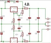
darkfenriz said:
hmmm... yes I did, why not?
Well, you neatly isolated the low Zout of the reg from the load! Your reg (when implemented well) will have a Zout of a few milli-ohms. (An ideal voltage source would be zero of course). Now with the 1 ohms, the Zout will be 1 ohms in parallel with the impedance of that cap, but that varies with frequency. You more or less throw away the reg with this!
What you could do is leave the R, C in but take the load, as normally done, from the reg, on the left side of the 1 ohms!
Your R,C will still damp the reg, and you still have low Zout. Eat your cake and have it too.
Anyway, I think that 1 ohms and the cap is really not necessary anyway. Any old crappy electrolytic will do. The crappier the better
")
Jan Didden
1 The LED is creating a constant voltage for the current generator formed by a teansistor and a resistor (22-100 ohms). The light is a nice side effect
2 No
3 The opamp tries to lower the output voltage. Inactive opamp = full output voltage. Base current through the pass transistor comes from the current generator.
ah so when picking an opamp, output current capabilities are not important. AD9631 should be a good alternative to AD825? It has 1.3kV / uS slew rate
maybe that opamp would be too fast and would not be stable.- Status
- This old topic is closed. If you want to reopen this topic, contact a moderator using the "Report Post" button.
- Home
- Amplifiers
- Power Supplies
- About Jung super regulator