ostripper said:
No comp, let's see now, unity gain will be in the MHZ, Cdom
will be the Cob of the tranny. Will make a good RF
amp..
OS
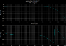
AC analysis of the compensated amp:
Attachments
Hi MJL21193
Have you thought of using a Foil Type 1uF and 0R8 (approx) in parallel with R35.
This is suppose to assist with the charge suckout mechanism (as described by Hugh) and Roender found that it had a very positive impact on bass control at high program levels. Roender used a 0R82/0.6W, metal film resistor in series with 1uF Vishay Roedestein mkp1839 to control ringing in driver transistors.
Have a look at Post #345 http://www.diyaudio.com/forums/show...111756&perpage=25&highlight=rmi&pagenumber=14
What do you think?
KLe said:Hi MJL21193
Have you thought of using a Foil Type 1uF and 0R8 (approx) in parallel with R35.
Hi KLe,
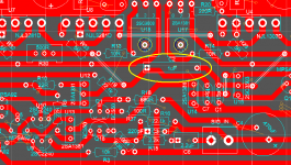
I need to post a more complete schematic. The board layout does have the cap you mention. although it is a regular poly film 1uF.
See the pic below - the yellow circle.
EDIT: No, I am wrong (as usual). That is not it and it is my intention of adding that cap. I will post a revised schematic and change the board layout to include it.
Attachments

By Kle - Have you spiced MJL21193's excellent amp, yet?
Yes, but I have "bastardized" it and replaced with standard
Vbe and my "frugal" 0281/0302's.
OS
ostripper said:
Yes, but I have "bastardized" it
Sacrilege!! You have ruined my art!!! Devil!!!!

It will probably work great with standard outputs and a Vbe multiplier - why not. According to the On-Semi application sheet, the TT transistors real benefit are realized when you want to run a higher idle current and avoid runaway. This is something that I want to do with this amp - run it at a higher idle current.

Sacrilege!! You have ruined my art!!! Devil!!!!

yes, but it simulates VERY good..
strange, but those 15p compensation caps act as shunt compen
sation in your amp (not Cdom) that's why you can run
without them...
The Cob of your trannies seems to be the only pole keeping this amp stable.
OS
ostripper said:
The Cob of your trannies seems to be the
only pole keeping this amp stable.
OS
I haven't ran it without the caps but curiosity is getting the better of me so I will try it on the second build. Just for the heck of it, you know
I have been doing some listening. Just the first prototype in mono. Amazing quality sound! I don't like to admit it, but it is better than my Patchwork
Bass is slightly more controlled, more powerful. Highs are cleaner and this is where I'm (and I'm going on deaf) hearing the biggest difference.This just means that I have some more work to do on my Patchwork to resolve the HF issues I guess.
I mentioned above about changes - I don't dare change this. This will stay as it is.
If I want to take the input stage in a different direction, I'll start a new thread and call it by another name. This one is here to stay.
MJL21193 said:
Amazing quality sound! I don't like to admit it, but it is better than ...
It would be much better if you put jfets in LTP. Also, separated power supply for input stage would provide better sound
roender said:Also, separated power supply for input stage would provide better sound
Absolutely

Now, when we simulate, we have +70 VDC and -70 VDC perfectly stable and perfectly clean supply.
So, we think these values we get will match reality.
Even if this amp will have a very good PSRR (power supply rejection)
there will be issues.
-------------
1. At higher output power there will be a sag. Maybe downto 65 VDC.
This will effect VAS headroom and operation, as well as current sources for input stage.
2. In addition there will be higher and higher RIPPLE on the supply lines.
The more current the higher ripple and higher frequency modulations disturbance.
Such filters as R36/R37 + capacitance can reduce the dirty supply, a bit.
But not fully.
-------------
Ideal voltage sources in Simulated circuits, will not be valid in reality.
This is one drawback with SPICE.
People will not learn and become aware (see those numbers) of the benefits of protecting the other stages
by giving OUTPUT one separate Supply for Loudspeaker currents.
Lineup
roender said:
It would be much better if you put jfets in LTP. Also, separated power supply for input stage would provide better sound
Hi roender,
I have the option on the board for a separate front end supply (see the terminals on either side of the board layout) . It's just to remove or not install R36 and R39. I may try this latter.
As for the fet input, then it would not be what it is - it would be your amp, right? besides, have you seen what I have for the differential pair on this amp?

Metal can, next to the small heatsink - LM394 super matched pair. Really, do you think a pair of jfets are better than this? I don't.
MJL21193 said:
LM394 super matched pair. Really, do you think a pair of jfets are better than this? I don't.
Yes, I think.
Try and see. Do not trust me ... or ask John Curl or Charles Hansen or Nelson Pass or Erno Borbely or Jonathan Carr or many others Gurus
lineup said:
Absolutely
Now, when we simulate, we have +70 VDC and -70 VDC perfectly stable and perfectly clean supply.
So, we think these values we get will match reality.
Even if this amp will have a very good PSRR (power supply rejection)
there will be issues.
Hi lineup,
My real supply is very stable at 72.6VDC - both rails. 20000uF of smoothing per rail. Not bad for a temporary supply.
Remember I simulate first, then I build a real amp to test and listen to.
lineup said:
1. At higher output power there will be a sag. Maybe downto 65 VDC.
This will effect VAS headroom and operation, as well as current sources for input stage.
2. In addition there will be higher and higher RIPPLE on the supply lines.
The more current the higher ripple and higher frequency modulations disturbance.
Such filters as R36/R37 + capacitance can reduce the dirty supply, a bit.
But not fully.
This amp is designed for an over sized power supply. Even though the supply will swing enough voltage for a power output of 250 watts into 8 ohms, it's input sensitivity (1.2Vrms) limits it to just 150 to 160 watts into 8 ohms. That allows room for transients without clipping. Rail sag will not be an issue and will not cause the problems that you assume. It should be fairly obvious that when the amp is operating at the point where the rails will sag significantly, the speakers will be producing enough db and distortion of their own to swamp any increased noise from the amp. Let's be sensible here.
An amp like this that has CCS and CM will have very good ripple rejection. That is the advantage of these mechanisms, as opposed to simple resistor loads or bootstrapping. Don't downplay their effectiveness in this.
MJL21193 said:
An amp like this that has CCS and CM will have very good ripple rejection. That is the advantage of these mechanisms, as opposed to simple resistor loads or bootstrapping. Don't downplay their effectiveness in this.
Did you measured the power supply ripple rejection? How do you know is high enough? What about PSRR at HF?
Do not forget that all voltage references (LEDs) are powered directly from PSU and not trough current sources
roender said:
Yes, I think.
Try and see. Do not trust me ... or ask John Curl or Charles Hansen or Nelson Pass or Erno Borbely or Jonathan Carr or many others Gurus
Quantify the improvement. I think that there is not much of a difference at all.
If all of the gurus jumped off a tall building, would I follow?
I know I would not hear the difference between a fet input and a bjt so I will not try it. I can not hear the difference between the LM394 and a well matched pair of BC550's either. I recommend that anyone who wants to build this amp to use the BC550 or MPSA18 for diff pair - just match them. I recommend that anyone who wants to have a jfet input, build yours. It's nice to have choices, right?
I would invite you to try my version but you have your mind made up already. Never underestimate the minds power to convince your ears what they are hearing.
- Status
- This old topic is closed. If you want to reopen this topic, contact a moderator using the "Report Post" button.
- Home
- Amplifiers
- Solid State
- Abomination! or Painting a Mustache on the Mona Lisa meets the Island of Dr. Moreau