Yep, your board has the trace error that needs to be fixed. Check out the PDF that I emailed to you - I also added it to my a40 web site. My wife makes fun of me for being a packrat, but you never know when you'll need something like old documentation ;-)
The TO-3 sockets that I have look like either A or C in the link you provided. I also see what you meant by mounting them without the sockets (mounting method E on the left of the link you posted). The best advantage I can think of for using the socket is to avoid overheating the transistor when soldering the wire leads.
Eric
Hey Eric, thanks this was the source of my problems all along. Amp is now totally silent and wires are no longer sensitive. Measured 57mv offset.
With everyone sleeping, I could only play a few seconds of music at low volume to see if it was working - sounded ok. JFET still in its orginal position. Will try at volume tomorrow and see how it sounds.
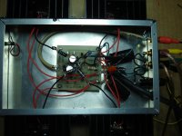
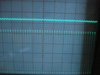
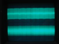
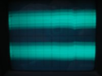
Still have the high frequency oscillation. Ignore top trace, just an open probe. Bottom trace, 200 millivots per div by .2us per div. That's in the megahertz range? How can that be?
It is also on the power supply rails. I will get a pic tomorrow.
Thanks again for the doc, that was the magic fix! On to channel 2...
Mitch
Attachments
Just to follow up...
2nd channel built and working. Used to warm up the bench overnight ;-) I installed snubbers on the bridges (47nf and 100ohm), but did not take out high frequency oscillation.
Moved amps to listening room and hooked up. No hum or buzz - Yay! Except for the transformer (mechanical - may have a few PS q's but another thread - too much fun listening!)
I am really amazed at how good the a40 sounds. My speakers are very efficient (98db @ 1w @ 1m) so plenty of headroom. Buddy Guy and his band sound like they are right in my listening room!
Thanks again Eric for finding that PCB mod from Old Colony - that was the ticket! Thanks to Rodeodave and others for the kind assistance.
Mr. Pass thanks again for your advice and fantastic sounding amplifier! The transient impact and damping control is incredible! Once the chassis covers arrive, I will post the finished project.
Cheers! Mitch
Attachments
Pass DIY Addict
Joined 2000
Paid Member
Hey Mitch,
Great to hear that things have improved and you're enjoying your "new" amps! I'm not sure how to modify the a40 in a similar manner, but in my Aleph-X page, the schematic that is next to the images of the PCB show the positions of C9 and C10. These caps are intended to solve high frequency oscillation on the output like you are describing. They are omitted from the circuit when there is no problem to solve. I'm not sure what the "analogous" position for them would be on the a40....
Perhaps someone with more knowledge can chime in here.
Congrats!
Eric
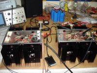
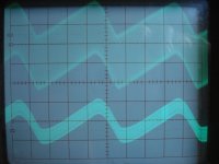
Thanks Eric. The high frequency noise is on the power supply rails as well. Attached are two pics - Left channel, 200mv per div and 5ms per div, +32vdc rail, stereo amps, top trace channel A, bottom channel B. Next pic is the same except for -32vdc.
Measured right at the pcb, which has a 4700uf 50v 3amp ripple current per rail local cap tied to star of that amp, which is where the ground of the probe was attached.
The power supply is the Old Colony ILP AA071 4 x 22v @ 5.5amps each from 1991. I replaced the old 10,000uf caps with 4 x 18,000uf 75vdc @ 10amp ripple current per cap. Also new 2 bridges 35amp 600piv, each with 4 x 47nf and 100ohm snubbers.
The transfomer is mechanically buzzing, on the bench it was a constant light buzz. In the listenting room, it cycles from light to heavy buzzing every 3 seconds. Maybe DC on the line in addition to high frequency noise? Would something like this work? http://www.hagtech.com/pdf/conditioner.pdf
Maybe I could use more capacitance in the power supply? Also, the implementation of the supply occurred before I found this site. Since I have seperate mono like amps (2 seperate chassis), I visually split the power supply to supply a left and right rail feed via 4ft of 14/3 to each chassis.
The power supply is wired throughout with 2 x 18 guage wire parallel and does go to a star ground. Since it is a prototype, I don't mind drilling holes as you can see I already have moved the components once already.
Perhaps I should place the transformer at one end and then the bridges, then the caps arranged so that a large bus bar can bolt all 4 cap together to ground like I see on on other PS builds on this site.
Thanks for any assistance.
Mitch
Attachments
Pass DIY Addict
Joined 2000
Paid Member
Hi Mitch,
A few thoughts about your questions. The power filter that you linked has potential to help, provided the trouble is actually coming from your wall outlet. Also, looking at the traces you have on your scope, I'm wondering why one is very thick (top right) while one is very thin (bottom left). Perhaps the caps are not "evenly" aged, or one is not capable of holding a charge as long? My a40 has 4x 56,000uF caps, one cap for each rail for each channel. My guess is that maybe 18,000uF is a bit small? I believe the original article specified 20,000uF. An easy thing to try is move all of your caps over to one channel so you get 36,000uF on both the positive and negative rail for one channel. Then see what you get in terms of ripple and speaker noise.
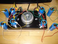
Other things to try: tightly twist the secondary leads coming from your transformer that go to each side. This will help to cancel/contain any RFI noise induced by your AC wiring. Also, mounting your caps this way presents a potential hazard if there are any small children/pets in your house, since the rail voltage is exposed to touch. Invert the caps and cut a hole in your chassis so the wires and termination points are inside your metal chassis. 2x18AWG may present a potential problem (I'm forgetting the rule on double runs and how that affects the resulting wire gauge - does 2x18ga make it behave like 15ga?). I would feel more comfortable running all power supply wiring in this chassis with 12ga wire or 14 at a minimum. 14ga tethers to the actual amps shouldn't present any problem.
A few thoughts about your questions. The power filter that you linked has potential to help, provided the trouble is actually coming from your wall outlet. Also, looking at the traces you have on your scope, I'm wondering why one is very thick (top right) while one is very thin (bottom left). Perhaps the caps are not "evenly" aged, or one is not capable of holding a charge as long? My a40 has 4x 56,000uF caps, one cap for each rail for each channel. My guess is that maybe 18,000uF is a bit small? I believe the original article specified 20,000uF. An easy thing to try is move all of your caps over to one channel so you get 36,000uF on both the positive and negative rail for one channel. Then see what you get in terms of ripple and speaker noise.
Other things to try: tightly twist the secondary leads coming from your transformer that go to each side. This will help to cancel/contain any RFI noise induced by your AC wiring. Also, mounting your caps this way presents a potential hazard if there are any small children/pets in your house, since the rail voltage is exposed to touch. Invert the caps and cut a hole in your chassis so the wires and termination points are inside your metal chassis. 2x18AWG may present a potential problem (I'm forgetting the rule on double runs and how that affects the resulting wire gauge - does 2x18ga make it behave like 15ga?). I would feel more comfortable running all power supply wiring in this chassis with 12ga wire or 14 at a minimum. 14ga tethers to the actual amps shouldn't present any problem.
Hey Eric, thanks.
re: power filter. When the fridge shuts off, I can hear the click through the mains on the speakers. Would a power filter filter that out? What about DC on the mains?
re: caps. Yeah, I was wondering that myself. Supposed to be new caps. I will put it back on the bench and swap things about to see if that if one of more caps is in not in good shape.
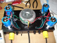
I tried adding more capacitance - see pic, it was only temporary and I pulled on the leads before I turned anything on. I just found it easier to hook up the caps and listen than drag it all down to the bench. It sounded cleaner in the top and bottom seemed more tight. Problem is those other caps are only 10,000uf and 20 years old.
4 x 56,000uf! Where did you get the caps from? I try Mouser or Digikey and they are like $50 a pop.
re: mounting caps, no worries - see the cage covers I have: http://www.diyaudio.com/forums/pass-labs/166784-pictures-your-diy-pass-amplifier-81.html
re: wiring - 2 x 18awg = 14 awg. I do have some good quality 12 awg speaker cable. Can I use that? If not, what do people reccomend?
Thanks again for your help Eric. I will put the amps back on the bench and take some more measurements. Just enjoying the sound too much to do that right now.
re: power filter. When the fridge shuts off, I can hear the click through the mains on the speakers. Would a power filter filter that out? What about DC on the mains?
re: caps. Yeah, I was wondering that myself. Supposed to be new caps. I will put it back on the bench and swap things about to see if that if one of more caps is in not in good shape.
I tried adding more capacitance - see pic, it was only temporary and I pulled on the leads before I turned anything on. I just found it easier to hook up the caps and listen than drag it all down to the bench. It sounded cleaner in the top and bottom seemed more tight. Problem is those other caps are only 10,000uf and 20 years old.
4 x 56,000uf! Where did you get the caps from? I try Mouser or Digikey and they are like $50 a pop.
re: mounting caps, no worries - see the cage covers I have: http://www.diyaudio.com/forums/pass-labs/166784-pictures-your-diy-pass-amplifier-81.html
re: wiring - 2 x 18awg = 14 awg. I do have some good quality 12 awg speaker cable. Can I use that? If not, what do people reccomend?
Thanks again for your help Eric. I will put the amps back on the bench and take some more measurements. Just enjoying the sound too much to do that right now.
Attachments
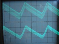
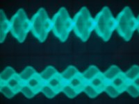
Inputs shorted. Outputs hooked up to speakers. Warm up 1/2 hour. Left channel takes longer to settle down than right.
Top tace left channel, bottom trace right channel.
First pic: 50mv per div, 2ms per div.
2nd: 50mv per div, 1ms per div.
3rd: 50mv per div, 1us per div.
Sorry for the blur... and many thanks for the assistance.
Top tace left channel, bottom trace right channel.
First pic: 50mv per div, 2ms per div.
2nd: 50mv per div, 1ms per div.
3rd: 50mv per div, 1us per div.
Sorry for the blur... and many thanks for the assistance.
Attachments
Can I just connect my scope to my PSU?, I'm so scared to break my new toy.
Careful, the scope's ground is usually connected to safety earth (earth ground)! That means you shouldn't measure voltage over components, that's what multimeters or floating scopes are for. Take measurements in reference to circuit ground.
Imagine an oscilloscope to be a 1M resistor that has one leg grounded. You can put the free leg anywhere in your circuit, but the other - grounded - leg can and will short things to ground.
In short, attach the probe's ground clip to circuit ground (and only to ground!) and feel free to poke anywhere you want with the probe's point.
Pass DIY Addict
Joined 2000
Paid Member
Hey Mitch,
Sorry not to have replied sooner - I was away for a few days. How are things behaving now? It seems like you've solved the audible buzz in your speakers. Do you still have the high frequency oscillation? I'm not sure what else to recommend to you if the oscillation is still present.
A power filter probably won't cure the fridge cutting out (or in). I think this is more a function of which leg from your circuit breaker things are connected to. My upstairs system has a huge 2000VA isolation transformer and then a Panamax power filter/distribution system (similar to the M4300-PM | A/V Components | Products | Panamax.com) and every now and then pops from appliances/lights switching off still get through.
My basement theater system has its own dedicated 30A run from the breaker box which goes directly into my DIY power filter and distribution system (it is also documented on my web page). I have never heard any stray pops or clicks from my theater system. My guess is that it has more to do with the dedicated run than the power filtration, but I don't really know.
There is no substitute for new(ish) caps - I've learned this one over and over again. I was trying to save money and only ended up with frustration as many of the surplus caps are so old that they don't really hold a charge anymore. The 56,000uF caps came from a supply house in Salt Lake City (Ra-Elco) that someone here pointed me to years ago. They carry surplus and used components. Also have a look at apexjr.com - Steve has lots a good stuff in stock and gets some very interesting things in from time to time. Another approach that a few here have used is to string together a bank of smaller 5,000-10,000uF caps until you get to something more substantial. I don't know that the cost is much different from finding one larger cap, but it may provide some additional flexibility with chassis construction.
What great looking amps you have now! The cages really do finish off your work making things look neat and clean! I really like the look!
I see no reason why you can't use a 12ga speaker cable for wiring your power supply. You just want the wires running from your rectifiers to your caps and ground point to be good and sturdy due to the high currents.
Sorry not to have replied sooner - I was away for a few days. How are things behaving now? It seems like you've solved the audible buzz in your speakers. Do you still have the high frequency oscillation? I'm not sure what else to recommend to you if the oscillation is still present.
re: power filter. When the fridge shuts off, I can hear the click through the mains on the speakers. Would a power filter filter that out? What about DC on the mains?
A power filter probably won't cure the fridge cutting out (or in). I think this is more a function of which leg from your circuit breaker things are connected to. My upstairs system has a huge 2000VA isolation transformer and then a Panamax power filter/distribution system (similar to the M4300-PM | A/V Components | Products | Panamax.com) and every now and then pops from appliances/lights switching off still get through.
My basement theater system has its own dedicated 30A run from the breaker box which goes directly into my DIY power filter and distribution system (it is also documented on my web page). I have never heard any stray pops or clicks from my theater system. My guess is that it has more to do with the dedicated run than the power filtration, but I don't really know.
re: caps. Yeah, I was wondering that myself. Supposed to be new caps. I will put it back on the bench and swap things about to see if that if one of more caps is in not in good shape.
I tried adding more capacitance - see pic, it was only temporary and I pulled on the leads before I turned anything on. I just found it easier to hook up the caps and listen than drag it all down to the bench. It sounded cleaner in the top and bottom seemed more tight. Problem is those other caps are only 10,000uf and 20 years old.
4 x 56,000uf! Where did you get the caps from? I try Mouser or Digikey and they are like $50 a pop.
There is no substitute for new(ish) caps - I've learned this one over and over again. I was trying to save money and only ended up with frustration as many of the surplus caps are so old that they don't really hold a charge anymore. The 56,000uF caps came from a supply house in Salt Lake City (Ra-Elco) that someone here pointed me to years ago. They carry surplus and used components. Also have a look at apexjr.com - Steve has lots a good stuff in stock and gets some very interesting things in from time to time. Another approach that a few here have used is to string together a bank of smaller 5,000-10,000uF caps until you get to something more substantial. I don't know that the cost is much different from finding one larger cap, but it may provide some additional flexibility with chassis construction.
re: mounting caps, no worries - see the cage covers I have: http://www.diyaudio.com/forums/pass-labs/166784-pictures-your-diy-pass-amplifier-81.html
What great looking amps you have now! The cages really do finish off your work making things look neat and clean! I really like the look!
re: wiring - 2 x 18awg = 14 awg. I do have some good quality 12 awg speaker cable. Can I use that? If not, what do people reccomend?
I see no reason why you can't use a 12ga speaker cable for wiring your power supply. You just want the wires running from your rectifiers to your caps and ground point to be good and sturdy due to the high currents.
Last edited:
Hey Eric, good to hear from you and thanks for asking.
The oscillation is still there. The caps did check out fine as I am getting 800mv pk to pk ripple on each leg of the supply at the amp boards. That's within spec and should be as they are new caps!
I am thinking it has to do with the power supply layout and wiring. I really did not think it through when I first built the supply (forgot my electronics from 20 years ago).
The AC and DC wires are pretty close together, I never twisted any of the AC wires and the AC wires going to the transformer is literally entwined with the wires of the star ground. Tsk tsk.
Further, my unorthodox layout of the power supply has the caps quite far apart, so the star ground wires probaly have the same if not more resistance than the DC supply wires and that I run the DC wires and ground through an unshielded cable to each of the amps some 4 feet away.
Plus here is evidence of AC oscillation on the GND: http://www.diyaudio.com/forums/pass-labs/192390-a40-oscillation-3.html#post2645027
So bottom line, I am going to re-lay out the Power Supply and rewire based on what I see on this forum. Plus a really thick ground and shorten the runs to the amp boards - I can probably lop off a foot on each supply run.
As soon as I can stop listening to them") !
!
PS thanks for the compliment on the cages and additional info you supplied.
The oscillation is still there. The caps did check out fine as I am getting 800mv pk to pk ripple on each leg of the supply at the amp boards. That's within spec and should be as they are new caps!
I am thinking it has to do with the power supply layout and wiring. I really did not think it through when I first built the supply (forgot my electronics from 20 years ago).
The AC and DC wires are pretty close together, I never twisted any of the AC wires and the AC wires going to the transformer is literally entwined with the wires of the star ground. Tsk tsk.
Further, my unorthodox layout of the power supply has the caps quite far apart, so the star ground wires probaly have the same if not more resistance than the DC supply wires and that I run the DC wires and ground through an unshielded cable to each of the amps some 4 feet away.
Plus here is evidence of AC oscillation on the GND: http://www.diyaudio.com/forums/pass-labs/192390-a40-oscillation-3.html#post2645027
So bottom line, I am going to re-lay out the Power Supply and rewire based on what I see on this forum. Plus a really thick ground and shorten the runs to the amp boards - I can probably lop off a foot on each supply run.
As soon as I can stop listening to them
!PS thanks for the compliment on the cages and additional info you supplied.
Pass DIY Addict
Joined 2000
Paid Member
A filtered EIC input may be of some help. I would recommend checking out Excess Soultions as they have a TON of surplus/used filters. I purchased from here for my DIY power filter.
Shortening and tightly twisting all of the wires in your power supply is likely to be of some help. I'm a bit surprised, though, by the level of ripple you are seeing on your caps. What is your final capacitance for each rail on each channel? I have 56,000uF and I see about 30-40mV of ripple. The output of my a40 runs a bit above spec at +/-32v and bias is about 3.1A per channel. The result is about 50w into either a 4ohm or 8ohm load before the onset of clipping.
I further isolated the power supply to the PCB from the output stage with a diode and a 4700uF cap and I get about 2-3mV ripple at the PCB.
Some time along the way, I also noticed strange (to me) behavior with my grounding scheme. If I connect the ground from each channel's power supply together and connect them to AC Mains ground through a CL-60 thermistor, I get hum at the speakers. Instead, if I use a bridge rectifier and connect the ground from each channel's power supply to the AC terminals of the bridge and then connect the AC Mains ground to the DC terminal of the bridge, I get no hum in the speakers... Still haven't figured this one out, but since I don't really care since I just went back to the bridge.
Mitchba,
Good work on the amp. It has a great look, and I admire your determination to clean up the output.
You may have some reactance issues with the wire going to the remote location of the output devices.
I built a version of the A40 about 25 years ago from the original Audio article. Giant power supply and ten inch tall heat sinks. All relevant parts were curve tracer matched...Great sound indeed!
The TO3 outputs were connected to the main proto board by about eight inches of wire and I had to attach the base resistors (R14, R15) directly to the device bases in order to get the amp to behave properly. Each TO3 base got its own resistor (total of four now), probably about 51.1 ohms each.
e.g., with you physical set-up, it may be beneficial to move the base resistors from the main PCB to the TO3 base leads to make the real part of the impedance larger than the imaginary part of the impedance, at these frequencies, at that location.
HTH,
DavidT
Hi Digits, I recently got a line conditioner but have not measured the PS or amps to see what it cleaned up. I can tell you that it greatly reduced the mechanical buzz of the transformer that only buzzed when my TV plasma display was on.
Hey Eric, I have 18,000 uf per rail in the PS and an additional 4,700 uf per rail right at the amp boards for a total of 90,800 uf for the stereo amp. These are all brand new caps. I noticed in the orginal Nelson Pass A40 article that 10,000 uf was used (and what came in the Old Colony Sound kit) for each rail. If you look at the scope traces in the article, the output is clean. As mentioned, I am going to rework the PS and if necessary I have room on the chassis for more caps and could do a CRC.
Hi DavidT, thanks for the compliment. After 20 years of thinking in the back of my mind to complete this amp, nothing is going to stop me now Thanks for the suggestion, I get what you mean. I will gve that a try.
I also need to noodle around more with the scope to see where the oscillation is coming from in order to isolate whether it is orginating from the amp or PS or both. Problem is, as I am typing this, I am enjoying the music too much to take the amps back to the bench!
Cheers, Mitch
Hey Eric, I have 18,000 uf per rail in the PS and an additional 4,700 uf per rail right at the amp boards for a total of 90,800 uf for the stereo amp. These are all brand new caps. I noticed in the orginal Nelson Pass A40 article that 10,000 uf was used (and what came in the Old Colony Sound kit) for each rail. If you look at the scope traces in the article, the output is clean. As mentioned, I am going to rework the PS and if necessary I have room on the chassis for more caps and could do a CRC.
Hi DavidT, thanks for the compliment. After 20 years of thinking in the back of my mind to complete this amp, nothing is going to stop me now
Thanks for the suggestion, I get what you mean. I will gve that a try.I also need to noodle around more with the scope to see where the oscillation is coming from in order to isolate whether it is orginating from the amp or PS or both. Problem is, as I am typing this, I am enjoying the music too much to take the amps back to the bench!
Cheers, Mitch
Pass DIY Addict
Joined 2000
Paid Member
I also need to noodle around more with the scope to see where the oscillation is coming from in order to isolate whether it is orginating from the amp or PS or both. Problem is, as I am typing this, I am enjoying the music too much to take the amps back to the bench! Cheers, Mitch
Ha, that's ALWAYS tough to take your amp out of service only to tear it apart and rework something that is relatively minor.
I have yet to pull my Aleph-X amps off the rack and do some additional measurements of bias points, track down some hum, and just clean up a few things. Its just too much fun listening!
- Status
- This old topic is closed. If you want to reopen this topic, contact a moderator using the "Report Post" button.
- Home
- Amplifiers
- Pass Labs
- a40 oscillation