I am trying to figure out what the differences are between these tubes. According to the valve museum the a2134 is the “commercial” version of the n78 but the data pages they link to look like very different tubes. Various places on the internet say that the n78 is similar to an el84 with a different pin out. I dunno, the data sheets kind of line up but not really. I saw an old discussion on here with @7N7 saying that GEC could be really generous with their ratings at times. Oh, and as an added bonus, how does the cv4062 figure into this? The valve museum says that they can be a “sensible” substitute for the a2134.

I hadn’t heard of a pentode series pass tube before, always associated that with a triode. So they are quite different tubes then. I popped both into my SE pentode amp. The n78 sounded quite a bit better. Once I have my push pull amp up and running again I will try them in that. The spec sheet for the n78 says that it can be run at 350v with 22ma into an 8k load. It’s hard to imagine such a small tube being able to take that kind of voltage but I guess the total dissipation is the important factor.
** ****************************************
* Created on 04/27/2024 10:32 using paint_kit.jar 3.1
* Plate Curves image file: /Users/zoran/Desktop/Model_Paint_Tools/Graph/
* Data source link:
*----------------------------------------------------------------------------------
.SUBCKT N75_triode 1 2 3 ; Plate Grid Cathode
+ PARAMS: CCG=12.2P CGP=1P CCP=12.2P RGI=2000
+ MU=26.16 KG1=375 KP=204 KVB=600 VCT=-0.25 EX=1.4
* Vp_MAX=550 Ip_MAX=110 Vg_step=1 Vg_start=2 Vg_count=25
* Rp=8000 Vg_ac=2.4 P_max=12 Vg_qui=-4 Vp_qui=220
* X_MIN=84 Y_MIN=18 X_SIZE=798 Y_SIZE=803 FSZ_X=1692 FSZ_Y=900 XYGrid=true
* showLoadLine=y showIp=y isDHT=n isPP=n isAsymPP=n showDissipLimit=y
* showIg1=n gridLevel2=n isInputSnapped=n
* XYProjections=y harmonicPlot=y dissipPlot=y
*----------------------------------------------------------------------------------
E1 7 0 VALUE={V(1,3)/KP*LOG(1+EXP(KP*(1/MU+(VCT+V(2,3))/SQRT(KVB+V(1,3)*V(1,3)))))}
RE1 7 0 1G ; TO AVOID FLOATING NODES
G1 1 3 VALUE={(PWR(V(7),EX)+PWRS(V(7),EX))/KG1}
RCP 1 3 1G ; TO AVOID FLOATING NODES
C1 2 3 {CCG} ; CATHODE-GRID
C2 2 1 {CGP} ; GRID=PLATE
C3 1 3 {CCP} ; CATHODE-PLATE
D3 5 3 DX ; POSITIVE GRID CURRENT
R1 2 5 {RGI} ; POSITIVE GRID CURRENT
.MODEL DX D(IS=1N RS=1 CJO=10PF TT=1N)
.ENDS N75_triode
*$
** ****************************************
* Created on 04/27/2024 10:15 using paint_kit.jar 3.1
* Plate Curves image file: /Users/zoran/Desktop/Model_Paint_Tools/Graph/
* Data source link:
*----------------------------------------------------------------------------------
.SUBCKT A2134_triode 1 2 3 ; Plate Grid Cathode
+ PARAMS: CCG=10.7P CGP=1P CCP=10.7P RGI=2000
+ MU=9.9 KG1=540 KP=54 KVB=720 VCT=0 EX=1.4
* Vp_MAX=320 Ip_MAX=110 Vg_step=2 Vg_start=4 Vg_count=20
* Rp=4000 Vg_ac=6.3 P_max=12 Vg_qui=-8 Vp_qui=143.5
* X_MIN=44 Y_MIN=16 X_SIZE=645 Y_SIZE=900 FSZ_X=1502 FSZ_Y=1005 XYGrid=true
* showLoadLine=y showIp=y isDHT=n isPP=n isAsymPP=n showDissipLimit=y
* showIg1=n gridLevel2=n isInputSnapped=n
* XYProjections=y harmonicPlot=y dissipPlot=y
*----------------------------------------------------------------------------------
E1 7 0 VALUE={V(1,3)/KP*LOG(1+EXP(KP*(1/MU+(VCT+V(2,3))/SQRT(KVB+V(1,3)*V(1,3)))))}
RE1 7 0 1G ; TO AVOID FLOATING NODES
G1 1 3 VALUE={(PWR(V(7),EX)+PWRS(V(7),EX))/KG1}
RCP 1 3 1G ; TO AVOID FLOATING NODES
C1 2 3 {CCG} ; CATHODE-GRID
C2 2 1 {CGP} ; GRID=PLATE
C3 1 3 {CCP} ; CATHODE-PLATE
D3 5 3 DX ; POSITIVE GRID CURRENT
R1 2 5 {RGI} ; POSITIVE GRID CURRENT
.MODEL DX D(IS=1N RS=1 CJO=10PF TT=1N)
.ENDS A2134_triode
*$
Attachments
I appreciate the info. Here’s where I’m confused, I keep hearing that that the a2134 can take more power but the GEC info says the n78 can be run at 350v as well as 250v as long as the bias is set correctly. Do we think the a2134 can use the same settings?Main diference in triode mode connection is
.
N78
Va=250V max.
Ri=2.1K
u=24
.
A2134
Va=300V
Ri=835 ohm
u=10
.
Acc. to data sheets tubes in triode mode are very linear and very usable for audio applications.
I have tried both in my SE pentode amp with varying success. 265v regulated on the screen and 300ish volts b+. The n78 sounded noticeably better with a much fuller sound. I will try them in triode push pull in the near future with 8k transformers. One of the reasons the n78 caught my eye was because at 350v it calls for 8k load. I was hoping the a2134 could be set up similarly.
The straightforward answer is that the N78 and A2134/CV4062 have quite different electronic properties. That means that each delivers their best when working with a different quiescent plate voltage and current ("operating point) with a different plate load.
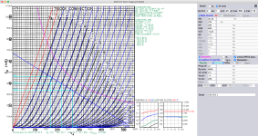
Let's do some quick and dirty estimates from the triode plate curves that Zoran has posted above.
These are the rough-as-guts estimates for operating the N78 and A2134 valves as triodes in Class A1. It shows that they will need different operating conditions of plate voltage (300V versus 185V), anode current (30mA versus 46mA) and grid voltage (-22V versus -14V). You could design a circuit in which the N78 and A2134 were "plug and play" substitutes, but I don't think it would get the best from either of them.
Let's do some quick and dirty estimates from the triode plate curves that Zoran has posted above.
- For the N78, the blue diagonal load line shown corresponds to a plate load a bit under 8kOhm. Choose an operating point on that line and about half way between the 0V and -22V grid voltage curves. For the N78, this is where the load line is cut by the -8V grid curve. Reading down from that point (the "operating point") to the horizontal axis, we get a plate voltage close to 300V (measured from the anode to the cathode). Reading across and left to the vertical axis, we get an anode current of about 38mA. We now have the quiescent conditions of Vak=300V ia=38mA at Vgk=-8V with a plate load of about 8kOhm. Now work left along the load line from the operating point to where the the load line is cut by the 0V grid curve and read off the plate voltage - it's around 130V. So, for this load line, the maximum voltage swing is about 300V-130V=170V. Square that (28900), divide it by 2 (14450) and divide that by the 7.9kOhm indicated plate load to get 1.8W output power into the load.
- Now for the A2134, we have an indicated plate load of about 4.6kOhm. I chose an operating midway between the 0V and -30V grid lines where the load line is cut by the -14V grid curve. That gives an operating point around 185V and 46mA. The 0V grid line cuts the load line at a plate voltage around 75V so that the maximum voltage swing is about 110V. That would deliver about 1.3W power into the 4.6kOhm plate load.
N78 | A2134 | |
| Rl (plate load) in kOhm | 7.9 | 4.6 |
| V quiescent (measured from the plate to cathode) | 300 | 185 |
| i quiescent in mA | 30 | 46 |
| V swing (maximum change in plate voltage, peak to peak) | 170 | 110 |
| P out (power delivered into Rl) in W | 1.8 | 1.3 |
These are the rough-as-guts estimates for operating the N78 and A2134 valves as triodes in Class A1. It shows that they will need different operating conditions of plate voltage (300V versus 185V), anode current (30mA versus 46mA) and grid voltage (-22V versus -14V). You could design a circuit in which the N78 and A2134 were "plug and play" substitutes, but I don't think it would get the best from either of them.
The data sheets for the N78 and the A2134 give typical pentode operating conditions for each. They are different, just as the triode operating conditions shown above are different. So plugging the A2134 into a circuit set up for the N78's "happy place" probably wouldn't work so well for the A2134 - it has a different "happy place" where it works best. In the circumstances, it probably is not quite "fair" to compare its sound with that of the N78.I popped both into my SE pentode amp. The n78 sounded quite a bit better.
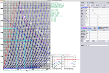
I’m still learning this stuff so thanks for the breakdown. I’ve been looking at the specs for the n78 http://www.r-type.org/pdfs/n78.pdf and they show two operating points for push pull triode one of them being 350v 23ma for 8k load. That is AB operation not A but the given distortion measurement seems quite good. I[‘ve never really understood where those distortion numbers came from. Surely there are a lot of variables left unsaid that got them to that measurement. Is that with or without feedback Etc.The straightforward answer is that the N78 and A2134/CV4062 have quite different electronic properties. That means that each delivers their best when working with a different quiescent plate voltage and current ("operating point) with a different plate load.
Let's do some quick and dirty estimates from the triode plate curves that Zoran has posted above.
- For the N78, the blue diagonal load line shown corresponds to a plate load a bit under 8kOhm. Choose an operating point on that line and about half way between the 0V and -22V grid voltage curves. For the N78, this is where the load line is cut by the -8V grid curve. Reading down from that point (the "operating point") to the horizontal axis, we get a plate voltage close to 300V (measured from the anode to the cathode). Reading across and left to the vertical axis, we get an anode current of about 38mA. We now have the quiescent conditions of Vak=300V ia=38mA at Vgk=-8V with a plate load of about 8kOhm. Now work left along the load line from the operating point to where the the load line is cut by the 0V grid curve and read off the plate voltage - it's around 130V. So, for this load line, the maximum voltage swing is about 300V-130V=170V. Square that (28900), divide it by 2 (14450) and divide that by the 7.9kOhm indicated plate load to get 1.8W output power into the load.
- Now for the A2134, we have an indicated plate load of about 4.6kOhm. I chose an operating midway between the 0V and -30V grid lines where the load line is cut by the -14V grid curve. That gives an operating point around 185V and 46mA. The 0V grid line cuts the load line at a plate voltage around 75V so that the maximum voltage swing is about 110V. That would deliver about 1.3W power into the 4.6kOhm plate load.
Rl (plate load) in kOhm V quiescent (measured from the plate to cathode) i quiescent in mA V swing (maximum change in plate voltage, peak to peak) P out (power delivered into Rl) in W
These are the rough-as-guts estimates for operating the N78 and A2134 valves as triodes in Class A1. It shows that they will need different operating conditions of plate voltage (300V versus 185V), anode current (30mA versus 46mA) and grid voltage (-22V versus -14V). You could design a circuit in which the N78 and A2134 were "plug and play" substitutes, but I don't think it would get the best from either of them.
My push pull amp has variable b+ and individual manual bias with 8k transformers and can run in triode or ultralinear. So I have quite a bit of leeway in setting it up. My SE amp is plug and play, made specifically to allow many different tube types to be used. I‘ve gotten good sound from a wide variety of tube combos but I’m under no delusions of what that means for measured performance. My push pull amp was also made specifically for tube rolling but it can get much closer to ideal performance because of the variable settings. So I’m looking for good starting points for the push pull amp.
the main factor in all applications is Internal resistances of these 2 tubes.
A2143 = 920 ohms cca.
N78 = 2000 cca.
In Triode mode.
That wil impact driving capabilities as souce, and if used as output tubes one with lower Ri will win with easier transformer choice - almost double less Henrys in prim inductance...
A2143 = 920 ohms cca.
N78 = 2000 cca.
In Triode mode.
That wil impact driving capabilities as souce, and if used as output tubes one with lower Ri will win with easier transformer choice - almost double less Henrys in prim inductance...
Manufacturers provided general data for designers to use - it was up to the designer to decide the application and the circuit, so the manufacturer's convention was to publish data for operating the valves WITHOUT the use of global negative feedback. The frequency of the input signal was not usually specified but was usually between 400Hz and 1000Hz.I‘ve never really understood where those distortion numbers came from. Surely there are a lot of variables left unsaid that got them to that measurement. Is that with or without feedback Etc.
My push pull amp was also made specifically for tube rolling but it can get much closer to ideal performance because of the variable settings. So I’m looking for good starting points for the push pull amp.
- Notice that the N78 data specifies both the grid bias voltage Vg1 AND the value of the cathode resistor Rk, which indicates that the data was most likely for the valve operating in cathode bias. A few data sheets will also cite the value of the cathode bypass capacitor used.
- Where grid bias is specified but Rk is NOT, it usually means that the measurements were taken with the valve operating in fixed bias. The first page of the Mullard EL84 data sheet is an example (here: http://www.r-type.org/pdfs/el84.pdf)
GEC specify one for the A2134 in push-pull using a 7.5kOhm plate to plate load (close enought to 8kOhm) though you WILL need to hold the screen supply voltage to 165V.
And go from there .... have fun!
- Home
- Amplifiers
- Tubes / Valves
- A2134 vs N78 tube