This is an interesting article.... It suggests that you don't need a high resistance thermistors to start a transformer.
http://dkc1.digikey.com/us/en/tod/Ametherm/NTC_NoAudio/NTC_NoAudio.html
http://dkc1.digikey.com/us/en/tod/Ametherm/NTC_NoAudio/NTC_NoAudio.html
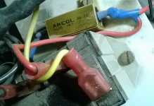
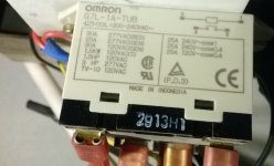
I use a relay (Omron 30A with a 200/240 coil for my 230 grid) and one 4,7 ohm Arcol power resistor to start up a 5 KVA toroid trafo (1:1) which in turn holds two 1,2KVA trafos etc.
The relay draw at 150 volt. Its arranged so that the load is on the 4,7 ohm resistor until the voltage has risen to 150 volt over the primary. Then the resistor is shortened by the relay.
Takes 2 components.
...
OK, ao you need 5 sec... what re you starting???
//
The relay draw at 150 volt. Its arranged so that the load is on the 4,7 ohm resistor until the voltage has risen to 150 volt over the primary. Then the resistor is shortened by the relay.
Takes 2 components.
...
OK, ao you need 5 sec... what re you starting???
//
Attachments
Last edited:
OK, ao you need 5 sec... what re you starting??
I'm not just using this to keep the fuse from blowing. I want the power supply to charge up slowly. This puts less stress on the other components that I will be using. The PS includes a capacitance multiplier circuit, and by charging it slowly I can make sure that the voltage drop across the transistors is kept low and other components are not stressed out. That's all.
the example is for a 2kVA 110Vac transformer.This is an interesting article.... It suggests that you don't need a high resistance thermistors to start a transformer.
http://dkc1.digikey.com/us/en/tod/Ametherm/NTC_NoAudio/NTC_NoAudio.html
As the transformer gets smaller the required resistance for effective current limiting goes up.
As the supply voltage doubles to 220Vac the required resistance roughly doubles for effective current limiting.
Take a 300VA 230Vac transformer as your example and work through the arithmetic. Or fit a T1.2A or T1.6A fuse and keep trying different NTC resistances until you find the value that prevents nuisance blowing of the close rated fuse for at least a years worth of use.
Last edited:
For slow charging, fit a slow charging circuit.
The NTC manufacturers show where to fit this and how to size them. This is the "normal" intended use for NTCs. They are fitted to all mains powered SMPS to limit the charging current going into the 400V capacitor. Electrolytics do not have a high dI/dT.
Your slow charging circuit goes in the capacitor circuit.
I need a delay of several seconds (e.g. 5sec or more) with the additional load in the circuit to cause a slow charge up of the main caps and other circuitry. Most ebay sourced soft starts don't connect the additional load for that long. The typical soft start that adds the load to the circuit for only the first few hundred milliseconds to prevent the initial large inrush won't work for me.
Can you elaborate on why you want something like a 5 sec delay, and how you would go about determining the 'additional load in the circuit' that would meet your requirement?
Long delays are usually related to some perception of valve heater rationale. Is it related to limiting peak currents in parts (compared to the max current the part would pass in normal operation), or a max dV/dt on a part, or reaching an operating temp in parts.
Someone asked me to post his here. I need a soft start for a 5000kV Transformer. what suggestions to you have?
post #23
+ schematic below.
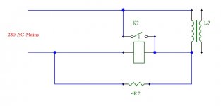
I start my trafos with this (I think).
But get a second opinion - no warranty and every possible disclaimer...
//
Attachments
Last edited:
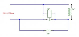
That makes more sense! Correct me if I am wrong, but I believe that the delay in your circuit is too small, considering that for that particular relay "must energize" voltage is 150V, probably a bit less, and time to energize is max 30ms, so that would give a delay of 1-2 cycles.
It is long enough to make my system being able to start or blowing my 10A fuses. I couldn't make it start without it and it has worked for 10 years+. But yes, it will not pamper your big capacitors. I keep my rig on mostly. But I clearly can hear the delay but it is short - less than a second.
That's safer.
But still no fuse.
Add a real timer to trigger the relay, not a voltage dependant RC
But then it's not *very* simple anymore
")
Transformer in-rush condition plus effective short circuited secondary condition would I reckon restrict the coil voltage quite a lot for many cycles, and hence meet the basic requirement. Of course, during that time the series resistor 'gets it in the neck' so needs to be a type with a good overload characteristic, and a value that will be somewhat of a compromise between delay time and power rating, and so the resistor becomes a 'not so simple' selection because it has mains on it. A digital cro is probably needed to see how much actual delay time you achieve, and whether you need to go to half-wave coil powering or not.
- Status
- This old topic is closed. If you want to reopen this topic, contact a moderator using the "Report Post" button.
- Home
- Amplifiers
- Power Supplies
- A very, very simple soft start circuit