I've made a start on the PCB and found a shortage of resistors. R2 and R9 (1.5R) are missing. Instead I have 2 extra 7.5K 
All the caps were present and correct.
All the caps were present and correct.
An externally hosted image should be here but it was not working when we last tested it.
An externally hosted image should be here but it was not working when we last tested it.
I suggest replacing the input and output jacks - usually the stuff available in China is of dismal quality.
Probably it was initially designed to be used with a different power switch, then they found something cheaper and neglected to adjust the cabinet............
Otherwise a very good find!
Keen to know the results!
Probably it was initially designed to be used with a different power switch, then they found something cheaper and neglected to adjust the cabinet............
Otherwise a very good find!
Keen to know the results!
Not including the the components with changed/different values -- how much of the kit pieces are you substituting and how much of it are you going to keep?
Just thought I would ask since you have it in front of you sometimes one can tell by the feel whether it is a cheap or good component.
Just thought I would ask since you have it in front of you sometimes one can tell by the feel whether it is a cheap or good component.
Not including the the components with changed/different values -- how much of the kit pieces are you substituting and how much of it are you going to keep?
Just thought I would ask since you have it in front of you sometimes one can tell by the feel whether it is a cheap or good component.
This all depends on how well the amp works (if at all). Then I'll have to decide if it's worth 'upgrading'. I've almost finished populating the PCB and expect to have it ready for powering up in the next day or two.
I have a mystery about R14. It's marked on the PCB but not shown on the schematic or listed in the parts list. It is referred to on the 'instruction sheet' but it's in Chinese
Bumped into this thread accidentally and subscribed...and now, after some very brief consideration, I put in an order. With shipping the total was $22.48 (USD), or in other words, about 17 €. Cheap as soap, as they say in Finland..
Albeit the power supply is probably a little weak for this project, it's a good starting point. I have some transformers that might be of use for this project, so I might substitute for a better one later on, but the aim is to build this as it comes, as stock as possible, to emulate best a beginner's situation at building something like this.
-Sale
That must be wrong as the amp weighs less than 1kg, probably about 1kg with packing. According to their shipping calculator, total shipping cost should be $20.66.I just got an email that stated that I'd have to pay another USD $22.31 to cover surprisingly high, increased postage costs for this delivery. I asked that my payment be refunded to my Paypal account and to forget it.
I'll just stick to my current LM4780 project...
-Sale
Anyway you did the right thing in cancelling as I've finished my amp and it doesn't work
There's a high hum level and distortion is about 99.9% using an old CD player as input source. I'm certain I have populated the board correctly so I don't know where to go from here seeing that I'm a total ignoramus on amp design.
There's the mystery of R14 as previously mentioned. I think this could be relevant. If only I understood Chinese! It looks to be on one of the LM324 pins.
An externally hosted image should be here but it was not working when we last tested it.
An externally hosted image should be here but it was not working when we last tested it.
An externally hosted image should be here but it was not working when we last tested it.
And this too:
An externally hosted image should be here but it was not working when we last tested it.
Any ideas anyone?
With the R14 jumper in place the amp actually works Sounds reasonable but there's some low level hum which could become annoying. The volume control is very sudden, either quiet or loud!
It could do with larger knobs to hide the nuts and oversize holes.
Sounds reasonable but there's some low level hum which could become annoying. The volume control is very sudden, either quiet or loud!An externally hosted image should be here but it was not working when we last tested it.
It could do with larger knobs to hide the nuts and oversize holes.
Any news on this unit yet regarding unwanted noise, etc.?
-Sale
An eagle-eyed guru (Peter Roberts) spotted another missing link. At the moment without the link the rectification is only half-wave and the likely cause of the hum. With the link in place rectification should be full-wave and hum-free but I haven't had an opportunity to fit the link yet.
Will post results in the next day or two.
An externally hosted image should be here but it was not working when we last tested it.
Incidentally I got Smalltao to edit the listing for the amp to show the correct weight and shipping charge. It should not cost more than 31.57 USD or 20 British pounds.
The hum could come from several sources. If you suspect the power supply, you can power it up with an external power supply and see if the hum changes or goes away.
Are the pots grounded to the chassis? I never liked that, and the industry moved away from it decades ago. It's possible (somewhat likely) that the hum comes from a combination of this and a poorly thought out grounding scheme. You did put some vinyl on the chassis, right? Did you make sure that the pots are grounded to the chassis?
As for the volume control, you can put some resistors in parallel with the wipers to ground. This will increase the attenuation of the pot and make the tracking much more accurate. Try a resistor around one third the value of the pot. Use 1 % resistors.
A poor solder joint or mistake stuffing the board could be the culprit, too.
The fact that you say that the volume control is way too sensitive tells me that this circuit wasn't given much thought in the design process, at least as far as gain structure is concerned. It was probably designed to use up stacks of old surplus parts. You should still be able to make it work as intended with a minimum of tweaking or mods. Once you know it's working correctly you can change a few things around.
Thanks for the ideas Fast Freddie D. I've tried moving the transformer out of the case so it's about 6" away from the PCB. No difference in hum level which rules out radiated noise. No difference either with grounding the pots.
I'm beginning to think that one of the weird rectifiers is faulty Would explain why fitting the missing link made little or no difference.
If anyone wants a nice little challenge to get their teeth into, I'm thinking of giving this amp away, free to a good home, just pay shipping.
Any takers?
I'm beginning to think that one of the weird rectifiers is faulty
Would explain why fitting the missing link made little or no difference.If anyone wants a nice little challenge to get their teeth into, I'm thinking of giving this amp away, free to a good home, just pay shipping.
Any takers?
Unfortunately I don't have the required parts to cobble together a power supply. One thing I have noticed is that the hum level drops to as good as zero when the volume is at max.
Now it's been pointed out by my tame guru (you know who you are) that the circuit designer was trying to build in a form of loudness control. This might have made sense if a more suitable pot had been used.
I am prepared to replace the vol pot rather than fiddle about with resistors. Any thoughts on the ideal value? I guess I need log one.
Cheers
Now it's been pointed out by my tame guru (you know who you are
) that the circuit designer was trying to build in a form of loudness control. This might have made sense if a more suitable pot had been used. I am prepared to replace the vol pot rather than fiddle about with resistors. Any thoughts on the ideal value? I guess I need log one.
Cheers
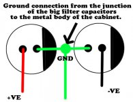
Could you kindly try the following. I solved my problem in this way.
Connect a wire from the junction of the filter caps to the ground( metal cabinet) .
Just make sure Audio chips are properly insulated from the ground/ metal cabinet.
Perhaps the humming problem could be fixed.
Connect a wire from the junction of the filter caps to the ground( metal cabinet) .
Just make sure Audio chips are properly insulated from the ground/ metal cabinet.
Perhaps the humming problem could be fixed.
Attachments
Last edited:
Unfortunately I don't have the required parts to cobble together a power supply. One thing I have noticed is that the hum level drops to as good as zero when the volume is at max.
Now it's been pointed out by my tame guru (you know who you are
I am prepared to replace the vol pot rather than fiddle about with resistors. Any thoughts on the ideal value? I guess I need log one.
Cheers
You said that the volume control was too sensitive. This coupled with the assertion that there is some kind of "loudness control" designed in, tells me that this part of the circuit is poorly thought out and designed to employ surplus parts.
You could use a linear pot with a parallel resistor. A 50K pot with a 14.7 K resistor in parallel with the wiper to ground would probably work. If you don't like it, try a different resistor.
Truth be known, I rarely calculate everything out precisely. I do some quickie calculations, then it's straight to the breadboard. If I don't like it, I change some stuff around. I take some measurements and make some changes. If this procedure fails me (it rarely does), then I do more careful calculations and analysis.
For some issues, super precise calculations only get you in the ballpark anyway
(like Miller capacitance) and you're back to trial and error to iron out the kinks.Unfortunately I don't have the required parts to cobble together a power supply.
Don't you ever strip old chassis? I always do. I have probably 50 salvage rectifier diodes. I have probably 30 transformers (most are suitable only for +/- 15 volt or 12 volt supplies @ 1 amp or so, but still handy). I have several sets of big caps I pulled out of old recievers etc. I have countless transistors; I have at least 100 LEDs that I pulled out of modems. I have switches, potentiometers, power resistors, chokes, fancy uber-expensive capacitors, etc, all salvage. These all get used in prototying and quick and dirty repairs. The only salvage parts I usually use in construction are "forever" parts like transformers, chokes, etc. But is makes design and prototyping very convenient and virtually free!
- Status
- This old topic is closed. If you want to reopen this topic, contact a moderator using the "Report Post" button.
- Home
- Amplifiers
- Chip Amps
- A very cheap TDA2030 Kit