The Leach Amp is one of the first articles I read online when I got the interest in building audio about 6 years ago. Many of the other designs I found were just schematics, with no other explanation other than "it just works like that, dont touch". The Leach Amp was thoroughly documented, with the reasons behind its design explained at every stage.
It happened exactly the same to me... only a couple of months ago.
Very sad news indeed. + Riposa In Pace +
About Vbe, as OS says, it does not look so simple to me. Beside the diodes it has a BJT as well (Q7) in order to have the possibility to adjust without the risk to bring in osclillations fron the cables coming from the main heatsink. Seems a smart idea.
I am also interested on buiding (when I will be done with my metal can BJT P3A).
I would love to make a version with TO3 finals , like the original. I have plenty of 15003/4 from my work spareparts.
effebi
This is very sad.
About 10 years age I contacted Dr Leach with a question and also asked if he would post his phono preamp articles and schematics. He responded that he had received numerous requests to post those old circuits and he intended to scan and post the material which he subsequently did. Dr Leach was surprised that anybody would still be interested in these old articles and he impressed me with his prompt answer to my question.
About 10 years age I contacted Dr Leach with a question and also asked if he would post his phono preamp articles and schematics. He responded that he had received numerous requests to post those old circuits and he intended to scan and post the material which he subsequently did. Dr Leach was surprised that anybody would still be interested in these old articles and he impressed me with his prompt answer to my question.
thanks os
yes, i have quite a few hs with 95 mm width
i like the right pcb , it'll save a lot of casing space.
if you don't mind me.... would you
rotate the 5watt resistor 45 degree or put it standing up to save space
and maybe add provisison for paraleled 1/2watt resistor to replace 5 watt resistor
use small decoupling capacitor for each output transistor
No issue with that , why ?? a certain HS ??
I have 2 styles.. A and B (below) I will use the same styles but include the whole amp (one board)."A" will go on a 75mm HS (3") "B" is supported by the OP's and needs a 127mm ( 5") HS. On these amps , one pair output devices njw0281/0302 with be the main drivers , this will allow it to be scaled into a MONSTER leach - 8-10 pair NJW21193/4 - 80V rails = 400w+ / 700W+ "super leach"
OS
I mailed Georgia Tech about it and apparently they've had lots of mails and messages from alumni of Dr Leach and others, requesting that his web site be kept up in his memory. They seem to be taking the requests pretty seriously, so here's hoping.
+10 ......
Very nice Ostripper.
BTW, I took a close look at zener diode current source as used in the Leach amp and was very pleasantly surprised at how good it works in sims. Its not quite as good at low frequencies as a transistor current source, but as soon as you get above about 2-3KHz, the transistor types start to slack off, and the zener source keeps on truckin' all the way out to a few hundred KHz. You need to spend some money on a rail decoupling cap and then a second one to filter out the zener noise, but that's all. I remeber reading somewhere that Marshal Leach preferred the 'sound' of the zener based LTP current source.
Any thoughts/expereince on this?
I think the simplicity and performance of the zener current source are what make it an attractive proposition here. The issue with the active current sources is that they start to behave less perfectly at higher frequencies - you have Cob, Early effect etc. The zener has none of that. Granted, it is noisier, and to overcome that you need to use the caps I mentioned above.
Most of the Leach designs have quite a bit of rail decoupling including a small electrolytic and film cap bypass on the Zeners, but I still see a few millivolts of ripple (mostly the input signal rather than 120 Hz ripple). More noise than I'd like in the residuals too; I was hoping to get around the zener noise.
Still, simplicity has a lot going for it, too.
Still, simplicity has a lot going for it, too.
Most of the Leach designs have quite a bit of rail decoupling including a small electrolytic and film cap bypass on the Zeners, but I still see a few millivolts of ripple (mostly the input signal rather than 120 Hz ripple). More noise than I'd like in the residuals too; I was hoping to get around the zener noise.
Still, simplicity has a lot going for it, too.
Everything will be as original as possible , except for the cascode/current sources. I will just use a decoupled resistive divider for the cascodes and a RED LED/2sc1845 for the current source. ZENER FREE DESIGN.
OS
+1 for that "Rest in peace professor"Maybe you can find a spot on the PCB for "WM Leach Jr (1940-2010) RIP" or something similar.
I think the simplicity and performance of the zener current source are what make it an attractive proposition here. The issue with the active current sources is that they start to behave less perfectly at higher frequencies - you have Cob, Early effect etc. The zener has none of that. Granted, it is noisier, and to overcome that you need to use the caps I mentioned above.
Temperature compensate a zener and its noise will be as low as a red LED if not lower, I bet on lower. Thats one of the design considerations of the goldmund current source among others that noone seems to to figure out yet .......
")
Very sorry to hear Prof Leach has passed away.
I built his amp using the offiicial V4.5 boards and as mahy of the original parts as I could find. I've built 10's of amps and this one might just be the closest to the fabled "straight wire with gain". Excellent sound and seemingly unflappable and unburstable.
I built his amp using the offiicial V4.5 boards and as mahy of the original parts as I could find. I've built 10's of amps and this one might just be the closest to the fabled "straight wire with gain". Excellent sound and seemingly unflappable and unburstable.
Dr. Leach is gone? Very sad. Very nice guy. I have a set of his last boards, so I'd better finish populating them and apply some power, and some speakers as a token of my respect.
..Todd
I saw a very nice colour layout of a Leach amp on his web site.
What happend with this project?
This is what i have had in my mind for a long time..
I want to build a high power Leach amp as a tribute and because i want the Leachs superb design but with a lot more power.
I have to do some redesigning but i am not confident in that, i am a fast learning novice.
My idea was the superamp, a bit mroe unusual than the original Leach amp. With more putput devices, holding it as close as possible to the original design.
You can´t deny that it would be a nice tribute with a 500w 8R Leach amp..
OSTripper, can you please pick thi project up again?
Peace//M
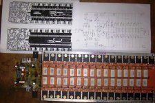
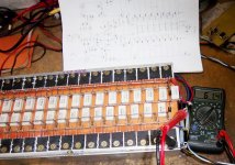
Tribute to Late prof. Marshal Leach.
Folks, attached photos of are amplifire made on basic circuit of Great Prf. Marshal Leach, Started in first shot, multimeter showing is peak output voltage that is around 62 volts on 80-0-80 D.C. rail,on 2 ohm's load. I tested this amp on even 0.5 ohm's load for 6 hours and got clear crispy sound, actually I connected 6 nos. 15" speakers + 10 nos. 12" speakers direct on one channel and played it full blast contunious for 6 hours and it gave me around 47 volt out put at that load.I salute Prof. for giving us all this Marvelous Circuit.
Folks, attached photos of are amplifire made on basic circuit of Great Prf. Marshal Leach, Started in first shot, multimeter showing is peak output voltage that is around 62 volts on 80-0-80 D.C. rail,on 2 ohm's load. I tested this amp on even 0.5 ohm's load for 6 hours and got clear crispy sound, actually I connected 6 nos. 15" speakers + 10 nos. 12" speakers direct on one channel and played it full blast contunious for 6 hours and it gave me around 47 volt out put at that load.I salute Prof. for giving us all this Marvelous Circuit.
Attachments
Sib,
note that Ved did not use the superamp sch.
The cascoded double barrelled was designed and adopted when devices with very good HV SOAR were almost unobtainable.
The cascode was a good solution.
Now we have the MJ21193/4 that work very well with high supply rail voltages.
note that Ved did not use the superamp sch.
The cascoded double barrelled was designed and adopted when devices with very good HV SOAR were almost unobtainable.
The cascode was a good solution.
Now we have the MJ21193/4 that work very well with high supply rail voltages.
Sib,
note that Ved did not use the superamp sch.
The cascoded double barrelled was designed and adopted when devices with very good HV SOAR were almost unobtainable.
The cascode was a good solution.
Now we have the MJ21193/4 that work very well with high supply rail voltages.
Thank you for the polite answer! I almost lost hope of this forum, last time i posted and you answer to me this:
If one doesn't have the skills to recognise one's own limitations then better to find another hobby.
With ill informed or uninformed guesses with mains electric then it's unwise to experiment with your own solutions
Thats why i seek help here, i recognise my own limitations. And i have another hobby. 2-stroke tuning, 3rd fastest in Sweden in my class in dragrace, and i race in roadracing on the same machine too. I recognize my limitatons. And i always try to stretch them and learn me more/ride faster and risking a crash.(Not in electronics) My bike has 23.5hp on the backwheel, from 70cc, that is stretching the limits and a very good achievement as the record in sweden is 26 hp. This is what i did in my first try. No need to build another bike.
AndrewT: Thank you, i learned that yesteraday evening.
I always liked your answers and what you write, you seem t know wery much. You made me a bit frustrated when you answered in that way to me..
I lokked up on your skills untill then. But, as you answred me in the right way now, wou have won back my respect for you.
Last edited:
Folks, attached photos of are amplifire made on basic circuit of Great Prf. Marshal Leach, Started in first shot, multimeter showing is peak output voltage that is around 62 volts on 80-0-80 D.C. rail,on 2 ohm's load. I tested this amp on even 0.5 ohm's load for 6 hours and got clear crispy sound, actually I connected 6 nos. 15" speakers + 10 nos. 12" speakers direct on one channel and played it full blast contunious for 6 hours and it gave me around 47 volt out put at that load.I salute Prof. for giving us all this Marvelous Circuit.
WOW!
What power output did you get? This is something i would like to build as i in the future will have a sub system using 10 12" drivers. It will be a low load i might think..
- Status
- This old topic is closed. If you want to reopen this topic, contact a moderator using the "Report Post" button.
- Home
- Amplifiers
- Solid State
- A tribute to the late Prof. Leach (LX amp / voltage stage)