Good point. You still need a top-flight DAC to match the dynamic range of a good conventional amplifier though.... by which I mean a TOTL consumer DAC chip in a first-rate implementation. We're talking 120+ dB here, not on paper but in real life.only if you actually NEED gain and a volume control.
unity gain is more than enough for most headphones with many modern sources, which also often have digital volume control, which is why the design is how it is.
Nothing a simple selectable resistive input attenuator couldn't fix, obviously, but that brings us back to the volume control topic.
Things probably work out better in real life than what you'd infer from this, as less sensitive headphones relax the requirements considerably. HD600s (102 dB / V) would need no more than 108 dB of DR abs max, and more like 88 dB in practice. That sounds better, doesn't it?
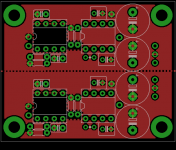
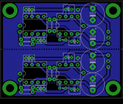
yep, agreed on the resist, I would remove any copper from under the buffer and around its input and output pins, particularly if its in widebandwidth mode. if your power supply is not that far away, I would increase the size of the decoupling caps and remove the reservoirs. as it stands, its also an RF risk, with input at one end of the board and the outputs right at the other end, with cables in and out, the plane and entire board can provide a path for RF/parasitics, as well as allowing a voltage to be created across the copper pour.
to that end, with a DIY PCB, I would tend to lose the copper pour on the top side altogether and just leave the entire bottom side solid copper as much as possible (but erode under in and out pins). as it is, the thin areas around the sides could easily cause ground currents and inductive RF currents to induce a voltage in the thin areas where it narrows. especially get rid of the islands where there is no reason for return signals to flow there deliberately.
to that end, with a DIY PCB, I would tend to lose the copper pour on the top side altogether and just leave the entire bottom side solid copper as much as possible (but erode under in and out pins). as it is, the thin areas around the sides could easily cause ground currents and inductive RF currents to induce a voltage in the thin areas where it narrows. especially get rid of the islands where there is no reason for return signals to flow there deliberately.
Last edited:
Well,I roll many opamps.LM4562,LME49720,OPA1612,NE5532,OPA2132,and now AD8599 in DIP adapter.Just everything runs fine,even AD8397(though it outs some offset).@GTrenchev, what sort of opamp are you using in there? Even if the LME49990 were available in DIP (it isn't), I'd assume a 100+ MHz GBW opamp at near unity gain wouldn't take kindly to sockets and a perfboard layout. Almost 80 dB of chsep driving 8 ohms is quite impressive though. That has to be power amp territory, in spite of a shared ground.
Look at some real experiments by some acknowledged analog experts - Jung's super regulators,Jim Williams's jitter measuremnets,DAC linearity and SMPS tests...most of them run on a breadboard or chaotic copper boards - and we're talking GHz range and nanovolt signals!
"The Wire" expression used for an amplifier "not coloring the sound" was used way before Owen's design.I dont see how this is 'the wire' at all, its bad enough publicly publishing a design that youve blatantly lifted the idea for and probably not asked permission or even informed Owen, but to just use the same name for a different design that has gone under no testing? I really dont know why you would do that? the layout is not worthy of the name IMO, traces crossing, no power or ground planes, no useful heatsink, vias all over the place, decoupling caps that are too far away, too physically large, on the end of a long trace with a via before the pin that will have very limited usefulness (OTT high quality decoupling and tight layout is what makes this amp shine), long feedback paths, traces that are too thin. huge long, thin traces from the main reservoir caps that are at the end of the board that has the lowest power demands and highest PSRR?
will all lme49990+lme49600 designs be called 'the wire' from now on? Owen designs very clean deliberately SMD for high performance and measures them to within an inch of their lives. I dont see that throwing a couple of the same parts onto a DIY PCB with no testing has anything to do with 'the wire'. and you are not the first to do this.
So nobody had to lift anything from anywhere for that, it is so to speak in public domain.
of course he didnt invent the term, can you really think its about the name itself having quoted and presumably read my post? or you didnt read it at all??
I guess you missed the obvious point, its got nothing to do with the name in isolation, its looking to his amp called 'the wire' using similar or the same parts except making it through-hole for the passives, then calling the amp 'the wire TH'
or you didnt read the first post either? or look at the eagle files linked in that first post? using basically the same parts placement, same opamp, same buffer, similar size etc for both the amp AND PSU boards
Why bring it up now to carry it on after that conversation is over and we are helping the OP with his amp regardless? hes using different parts now and basically I dont want to carry it on, I made my point and Owen now has new 4 layer updated boards available anyway. Do you think this is productive given your clear lack of understanding of what you are talking about? you are trolling.. thats why. please desist.
I guess you missed the obvious point, its got nothing to do with the name in isolation, its looking to his amp called 'the wire' using similar or the same parts except making it through-hole for the passives, then calling the amp 'the wire TH'
or you didnt read the first post either? or look at the eagle files linked in that first post? using basically the same parts placement, same opamp, same buffer, similar size etc for both the amp AND PSU boards
Why bring it up now to carry it on after that conversation is over and we are helping the OP with his amp regardless? hes using different parts now and basically I dont want to carry it on, I made my point and Owen now has new 4 layer updated boards available anyway. Do you think this is productive given your clear lack of understanding of what you are talking about?
you are trolling.. thats why. please desist. Hey, guys. I recently found the "the wire" here on this forum and wanted to build one for myself. Given the lack of boards and the fact that I have loads of through-hole parts laying around, I decided to try my hand at designing a through-hole version of the PSU and SE-SE boards. I tossed it together in eagle. Everything's included in the zip. If anyone feels like doing some sanity checking or giving some feedback on any improvements that could be made, I would appreciate it. Thanks.
Last edited:
- Status
- This old topic is closed. If you want to reopen this topic, contact a moderator using the "Report Post" button.
- Home
- Amplifiers
- Headphone Systems
- A Through-hole "Wire" Amp