I've used the AT BP4025 stereo mic extensively for SFX and ambience recording with excellent results. My problem is with the heaviness of the rig: BP4025 in blimp + MiniMe + MicroTrack II as bit-bucket + custom battery power unit. It's a lot of stuff hanging off my neck!
I recently got a Sony PCM-M10 recorder and it occurred to me that it and the BP4025 would be a simple and excellent match.
Important Specs about the BP4025:
Open-Circuit Sensitivity: -32 dB (25.1 mV) re 1V at 1 Pa (96 dB SPL)
Impedance: 170 ohms
Output is transformer balanced.
Dynamic Range: 131 dB, 1kHz at Max SPL
Signal-to-Noise Ratio: 80 dB, 1kHz @ 1 Pa (96 dB SPL): Very quiet!
Phantom Power Requirements: 11-52V DC, 7ma typical (both channels total). AT support claims no difference in electrical specs if within this PP range)
Important Specs about the PCM-M10:
Signal-to-Noise Ratio: 87 dB (1kHz IHF-A) (for 24 bit), line in to line out. Also very quiet!
Line-in Jack Impedance: 22 kohms
Line-in Jack Minimum Input Level: 500 mV
Line-in Jack Rated Input Level: 2 Volts.
Both the mic and the m10 have HP filters and attenuation pads. The M10 is equipped with a limiter as well.
After looking at various commercial solutions, it seems to me that this would be an easy and relatively cheap DIY as a custom solution; it could also be easily adapted to other mics. Important parameters are low-noise, low current, good CMRR at the front end, low distortion figures, good linearity; the unbalanced connection to the recorder will be very short. Since the mic can be powered by as little as 11 volts, 2x9 volt solution could easily power 2 opamps; 18v across both batteries could easily provide PP for the mic and a simple comparator turning on a flashing LED could provide warning of low voltage status. Two hours would be adequate running time (more looks possible, maybe doubling the batteries, but I'll have to test for this; 2 batts would be more elegant) and an external jack for external battery or AC adapter could be easily provided.
At first I thought of using the M10 mic inputs, but the problem is with most opamps is that noise performance at low gains is degraded. So it makes sense to use the opamp as a pre to improve the noise performance, especially since the M10 line-in can take the input level. Based on the mic sensitivity, 20x gain (+27 dB) would yield the nominal min 500 mV figure for the M10's line inputs, with plenty of margin for additional input. Anyway, my plan is to include an on-board trimmer adjustment of gain for fine tuning.
So far some OpAmp candidates I'm considering are:
NE5532: bipolar, noise 5 nV/√Hz at unity gain, input impedance 300 kOhm, operating voltage +/- 5 to +/- 15, current at idle: 8-16 ma, Slew Rate 9v/us, UGB 10 MHz
OPA2132: FET, noise 8nV/√Hz at 1kHz, input impedance 60 MHz, operating voltage +/- 2.5 to +/- 18, current at idle 8-8.8 ma, Slew Rate 20V/us, GBP 8 MHz
INA217: bipolar, noise 1.3 nV/√Hz at 1 kHz, operating voltage +/- 4.5 to +/- 18, current at idle 20-22 ma, Slew Rate 15V/us, Bandwidth 800k @ G=100
THAT 1512: bipolar, noise 4.6nV/√Hz at 20 dB gain, input impedance 10-15 k, operating voltage +/- 5 to +/- 20 V, current 6-8 ma, Slew Rate 19 V/us, Bandwidth at 20dB gain = 9 MHz.
My vote from this list is for the That 1512. Apart from performance, current consumption looks like it would be 12 ma for the 2 preamps and 7 ma for the mic; if my calc is correct, I should get around 30 hours from 2 alkaline 9-volts. Based on this choice the circuit would look like the complete phantom powered circuit in the data sheet, with the addition of the gain mod and 10 ohm build-out to a coupling cap; I have some fine caps for this.
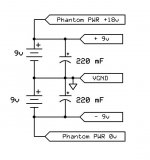
The battery power would be set up like this:
http://www.diyaudio.com/forums/attachment.php?attachmentid=492903&stc=1&d=1436513500
One consideration is that at these voltages, it might be better to use a lower phantom power resistor value than the usual 6k8's. This Shure support post shows 2k2 being used instead, with an 18 volt (2x 9v) PP source.
However considering the low current consumption of this circuit, I'm tempted to use a single battery with a MAX1044 as shown on this page. This would allow battery swapping for longer recordings, but the max freq it can run at is 60 kHz, which means that it'll pollute the audio if I record at 96 kHz. Maybe there's better candidates for this chip out there? Or maybe just KISS...")
I'm also stumped on a low power single channel comparator and flashing LED driver to show low battery power. It looks like a low power single channel comparator should be used with a transistor for the LED driver. Any ideas for this are welcome. I'd also rather power this from the entire 18v line than tagging it onto the +9v side of the bipolar circuit to keep consumption even; from some quick research that could be a problem.
BTW, I'd be using mini-XLR connectors to minimize wiring size and runs; 5-pin from the mic, and 3-pin to 1/8" unbalanced.
I'm pretty competent with analog circuitry, but I'm definitely not an EE, so I'd appreciate a few comments and observations on my research and proposed schematic and component choices from the more knowledgeable builders on this board. Could be I'm overthinking this and there's a simpler and more elegant solution. The Denecke PS-2 was the last hardware I was seriously considering, but it doesn't preamplify and my feeling is I'd get better performance from a preamp topology using the M10.
TIA for any feedback!
I recently got a Sony PCM-M10 recorder and it occurred to me that it and the BP4025 would be a simple and excellent match.
Important Specs about the BP4025:
Open-Circuit Sensitivity: -32 dB (25.1 mV) re 1V at 1 Pa (96 dB SPL)
Impedance: 170 ohms
Output is transformer balanced.
Dynamic Range: 131 dB, 1kHz at Max SPL
Signal-to-Noise Ratio: 80 dB, 1kHz @ 1 Pa (96 dB SPL): Very quiet!
Phantom Power Requirements: 11-52V DC, 7ma typical (both channels total). AT support claims no difference in electrical specs if within this PP range)
Important Specs about the PCM-M10:
Signal-to-Noise Ratio: 87 dB (1kHz IHF-A) (for 24 bit), line in to line out. Also very quiet!
Line-in Jack Impedance: 22 kohms
Line-in Jack Minimum Input Level: 500 mV
Line-in Jack Rated Input Level: 2 Volts.
Both the mic and the m10 have HP filters and attenuation pads. The M10 is equipped with a limiter as well.
After looking at various commercial solutions, it seems to me that this would be an easy and relatively cheap DIY as a custom solution; it could also be easily adapted to other mics. Important parameters are low-noise, low current, good CMRR at the front end, low distortion figures, good linearity; the unbalanced connection to the recorder will be very short. Since the mic can be powered by as little as 11 volts, 2x9 volt solution could easily power 2 opamps; 18v across both batteries could easily provide PP for the mic and a simple comparator turning on a flashing LED could provide warning of low voltage status. Two hours would be adequate running time (more looks possible, maybe doubling the batteries, but I'll have to test for this; 2 batts would be more elegant) and an external jack for external battery or AC adapter could be easily provided.
At first I thought of using the M10 mic inputs, but the problem is with most opamps is that noise performance at low gains is degraded. So it makes sense to use the opamp as a pre to improve the noise performance, especially since the M10 line-in can take the input level. Based on the mic sensitivity, 20x gain (+27 dB) would yield the nominal min 500 mV figure for the M10's line inputs, with plenty of margin for additional input. Anyway, my plan is to include an on-board trimmer adjustment of gain for fine tuning.
So far some OpAmp candidates I'm considering are:
NE5532: bipolar, noise 5 nV/√Hz at unity gain, input impedance 300 kOhm, operating voltage +/- 5 to +/- 15, current at idle: 8-16 ma, Slew Rate 9v/us, UGB 10 MHz
OPA2132: FET, noise 8nV/√Hz at 1kHz, input impedance 60 MHz, operating voltage +/- 2.5 to +/- 18, current at idle 8-8.8 ma, Slew Rate 20V/us, GBP 8 MHz
INA217: bipolar, noise 1.3 nV/√Hz at 1 kHz, operating voltage +/- 4.5 to +/- 18, current at idle 20-22 ma, Slew Rate 15V/us, Bandwidth 800k @ G=100
THAT 1512: bipolar, noise 4.6nV/√Hz at 20 dB gain, input impedance 10-15 k, operating voltage +/- 5 to +/- 20 V, current 6-8 ma, Slew Rate 19 V/us, Bandwidth at 20dB gain = 9 MHz.
My vote from this list is for the That 1512. Apart from performance, current consumption looks like it would be 12 ma for the 2 preamps and 7 ma for the mic; if my calc is correct, I should get around 30 hours from 2 alkaline 9-volts. Based on this choice the circuit would look like the complete phantom powered circuit in the data sheet, with the addition of the gain mod and 10 ohm build-out to a coupling cap; I have some fine caps for this.
The battery power would be set up like this:
http://www.diyaudio.com/forums/attachment.php?attachmentid=492903&stc=1&d=1436513500
One consideration is that at these voltages, it might be better to use a lower phantom power resistor value than the usual 6k8's. This Shure support post shows 2k2 being used instead, with an 18 volt (2x 9v) PP source.
However considering the low current consumption of this circuit, I'm tempted to use a single battery with a MAX1044 as shown on this page. This would allow battery swapping for longer recordings, but the max freq it can run at is 60 kHz, which means that it'll pollute the audio if I record at 96 kHz. Maybe there's better candidates for this chip out there? Or maybe just KISS...
I'm also stumped on a low power single channel comparator and flashing LED driver to show low battery power. It looks like a low power single channel comparator should be used with a transistor for the LED driver. Any ideas for this are welcome. I'd also rather power this from the entire 18v line than tagging it onto the +9v side of the bipolar circuit to keep consumption even; from some quick research that could be a problem.
BTW, I'd be using mini-XLR connectors to minimize wiring size and runs; 5-pin from the mic, and 3-pin to 1/8" unbalanced.
I'm pretty competent with analog circuitry, but I'm definitely not an EE, so I'd appreciate a few comments and observations on my research and proposed schematic and component choices from the more knowledgeable builders on this board. Could be I'm overthinking this and there's a simpler and more elegant solution. The Denecke PS-2 was the last hardware I was seriously considering, but it doesn't preamplify and my feeling is I'd get better performance from a preamp topology using the M10.
TIA for any feedback!
Attachments
Last edited:
Well, theyhave been ignoring you.
Other than trimming the gain I'm not sure what you are doing with the op amps. You havn't said what gains you intend to run. The 5532 is good at unity gain but not well specified at say, 10.
Your THAT op amp seems okay if a little slow. I don't know if you are going to record bells cymbals or top octave piano with a lot of High Frequencies but I do. I have had some luck with ST 33078 @50x for mag phono use. They are very hiss free and sound good. They do require 30 pf areound the feedback resistor and local -.1 uf bypass cap from rail to rail, to not oscillate. 33078 consume about 2.5 ma per section or 5 ma for the 2 channel DIP.
I don't know what you mean by "PP". Phantom Power?
I'd use two jfets for the low batt detector, one plus zener for the detection, another as a timer to run a blink cap and restart the cycle. I use J111 since I can't buy J170 anymore. Jfets run okay on a megohm drive. Or 2n7000 nfet if you cant get the jfets to work.Finding a LED that works at less than 10 ma (the standard drive) seems to be key on 9v batteries.
Most of these portable recorders like zoom and tascam do the phantom power and input for condensor mikes okay, the limitation is the stereo 1/8 phone plug input, for which you have to build a custom cable. See some recent conversations about on-site recording on chat of organforum.com. Your mike is about 2 db less sensitive than my Shure KSM27, which doesn't hiss.
Good luck.
Hi, have a look at the AD797 too
I think you are confused about Phantom Power, PP is what powers electrec Mics.
I can design low power single channel comparator with flasing LED for you, as i've done it before. You need to let me know what you define as the low battery voltage.
I think you are confused about Phantom Power, PP is what powers electrec Mics.
I can design low power single channel comparator with flasing LED for you, as i've done it before. You need to let me know what you define as the low battery voltage.
The battery power would be set up like this:
Are you sure the phantom power can be connected as you show?
Can you post the complete circuit?
Wow! Thanks guys for the feedback; I was almost considering this thread a wasted effort...
To all: my use of "PP" is just as abbreviation for "Phantom Power". That's it.
@indianajo:
Actually I did: since the line input on this recorder is quieter than the mic input, the op amps are preamps, and gain is going to be somewhere between +27 dB and +40 dB. I'll have to fine tune that and was planning on using a ballpark resistor + fine trimmer to adjust the gain to the recorder for both channels.
@Zero D:
@rayma:
To all: my use of "PP" is just as abbreviation for "Phantom Power". That's it.
@indianajo:
Other than trimming the gain I'm not sure what you are doing with the op amps. You havn't said what gains you intend to run.
Actually I did: since the line input on this recorder is quieter than the mic input, the op amps are preamps, and gain is going to be somewhere between +27 dB and +40 dB. I'll have to fine tune that and was planning on using a ballpark resistor + fine trimmer to adjust the gain to the recorder for both channels.
My intent is to make as light a rig as possible to record environmental/ambientsounds, which includes very subtle shading of sound in all registers; so accuracy and sensitivity, low noise and distortion are all very important. The 33078 is a very interesting choice. But the slew rate on the THAT1512 is better: 19 v/us vs 7 v/us on the 33078. distortion figures are comparable, but it does use less power. However for noise, the 33078 comes in specified at 4nV/√Hz at 1kHz, but there's no additional info or graph I can find that specifies if this is constant at all gain settings. In contrast the 1512, shows that as gain increases above +20 dB to +40 dB, noise actually decreases from 4.6nV/√Hz to 1.4nV/√Hz.Your THAT op amp seems okay if a little slow. I don't know if you are going to record bells cymbals or top octave piano with a lot of High Frequencies but I do. I have had some luck with ST 33078...
I don't know how many bookmarks I made on the subject, but this is turning out to be the most complex part of the build! I need a circuit that will run on 18v (2x 9v), consume the least amount of power possible until the trip voltage is reached (13v seems adequate) and then power a low-power flashing LED to let me know that the battery needs replacing but without quickly draining what's left of the battery and giving me some operational time. BTW, it also needs to be perfectly silent! I don't want to hear any electrical artifacts on the recordings. I'm not sure about the 13v; the mic will cut out if the phantom power drops below 11v. Depending on 9v alkaline depletion curves, I suspect a higher voltage might be better (14v? 15v?)I'd use two jfets for the low batt detector, one plus zener for the detection, another as a timer to run a blink cap and restart the cycle. I use J111 since I can't buy J170 anymore. Jfets run okay on a megohm drive. Or 2n7000 nfet if you cant get the jfets to work.Finding a LED that works at less than 10 ma (the standard drive) seems to be key on 9v batteries.
Actually the PCM=M10 battery power seems to be around 3v, so it's OK for small ECM mics, but totally inadequate for a pro-grade mic. It just so happens the BP4025 doesn't need more than 11v to run to spec. Thanks for your other comments and suggestions.Most of these portable recorders like zoom and tascam do the phantom power and input for condensor mikes okay, the limitation is the stereo 1/8 phone plug input, for which you have to build a custom cable.
@Zero D:
It's a great chip, I admit, but the current consumption is higher than the 1512.Hi, have a look at the AD797 too
Now that would be awesome! You can read the specs in the text above. What would a good trip point be?I can design low power single channel comparator with flasing LED for you, as i've done it before. You need to let me know what you define as the low battery voltage.
@rayma:
I haven't laid out everything, but I will once I'm done. I don't see why it couldn't: the outside legs would likely have a capacitor across them as well. 18v to the phantom, +/- 9 to the opamps... am I missing something? In principle the phantom power is isolated from the preamp from the two DC-blocking caps on the input arms, so it should be OK.Are you sure the phantom power can be connected as you show?
Can you post the complete circuit?
I haven't looked at your phantom circuit, but all you need is clean 11v. Match the phantom resistors as closely as possible, no tolerance is too small.
You listed opamps and inamps both. What you want are inamps, designed exactly for what you are doing, balanced in >> unbalanced out. That 1512/INA217 fit the bill.
The M10 is not noisy, you will probably not get much quieter, but the top end is a little slow.
What are you doing for trim/gain, pots? You will need trimmers if so because of too loose tolerances, and in stereo recording you want gains matched evenly. Maybe one 5 pin mini connector instead of two. If you are doing stepped switch gain, how many gain settings? And think about quality switches/size/mounting. Don't underestimate the casework.
Also recommend designing for variable phantom as this microphone will probably not be your last. <And then I can use it when you finish > What run times do you need?
This is what you want but it's discontinued http://naiant.com/tinybox-specification/
You listed opamps and inamps both. What you want are inamps, designed exactly for what you are doing, balanced in >> unbalanced out. That 1512/INA217 fit the bill.
The M10 is not noisy, you will probably not get much quieter, but the top end is a little slow.
What are you doing for trim/gain, pots? You will need trimmers if so because of too loose tolerances, and in stereo recording you want gains matched evenly. Maybe one 5 pin mini connector instead of two. If you are doing stepped switch gain, how many gain settings? And think about quality switches/size/mounting. Don't underestimate the casework.
Also recommend designing for variable phantom as this microphone will probably not be your last. <And then I can use it when you finish
> What run times do you need? This is what you want but it's discontinued http://naiant.com/tinybox-specification/
Last edited:
I'm very familiar with the process of matching components and generally try to match to at least 1%, and a decade better if I can. My plan is to build the preamps, run tests with the Mic picking up test tones and audio from my monitoring system to find the target gain that would work best with this mic/rec combo. Then use a solid resistor for 90% of the resistance and a 20-turn to fine tune the last 10% and make sure both sides are accurately balanced.What are you doing for trim/gain, pots? You will need trimmers if so because of too loose tolerances, and in stereo recording you want gains matched evenly.
1 5-pin is likely, since the other is unbalanced stereo. And I know all about casework... which is why I was planning on making this project as simple and brainless as possible. Probably 1 power switch, the battery LED, the mini-XLR, and the stereo unbalanced, which I might just simply run out of the box without a jack. But I may future proof the design somewhat with internal jumpers. Like I mentioned originally, both the mic and the recorder have attenuation pads and Highpass filters, and with the recorder's adjustable gain I think I can manage to work without having to add anything else to the preamp.Maybe one 5 pin mini connector instead of two. If you are doing stepped switch gain, how many gain settings? And think about quality switches/size/mounting. Don't underestimate the casework.
Well, the whole point of this is that this preamp is "targeted" to one specific mic and recorder, which makes it possible to cut some corners.Also recommend designing for variable phantom as this microphone will probably not be your last. <And then I can use it when you finish
For a number of reasons, designing for use with other mics introduces compromises the most important of which are increasing the circuit complexity and the power consumption. Runtime? Basically as much time as I can draw from 2 x 9v batteries. IIRC, a calc I did a few days ago seems to show that I should be able to get more than 10 hours out of this circuit.Actually, that's EXACTLY what I wanted! Before I engaged the idea of building this preamp, I was looking for an off-the-shelf solution and everything pointed to the Naiant box, which is sadly discontinued. Actually I was pretty surprised to find that many smaller manufacturers of these kinds of preamps have up and disappeared. Thanks for the link, BTW; till this one all the links I found were dead. And I can't seem to find a single picture of the box anywhere...This is what you want but it's discontinued tinybox specification - Naiant Studio
Last edited:
Understood on all points.
One other possibility is Oade or Busman mod tascam dr100 or similar. They put out phantom, conversion on all the portables is roughly on par, and if you have them upgrade the preamp circuitry it will probably sound very similar to what you're planning building, and it cuts everything down to one box.
One other possibility is Oade or Busman mod tascam dr100 or similar. They put out phantom, conversion on all the portables is roughly on par, and if you have them upgrade the preamp circuitry it will probably sound very similar to what you're planning building, and it cuts everything down to one box.
The phantom power setup should work, but one would have to pay attention to the fine points of converting a split-power circuit to single-ended, as discussed over here for something quite similar. If phantom power is to be turned off, input coupling caps would also have to be bipolar types (or two polar ones back-to-back).
If you are already using the +18V to supply your main circuit, some reasonably extensive filtering of the phantom power tap seems like a good idea. While CMRR should keep any kind of crosstalk in check reasonably well, it's better to be safe than sorry.
For a pro mic you always need a balanced input, and a instrumentation amplifier setup really is the way to go. The usual INAs/THATs/SSMs with their matched resistors should have good CMRR, while with a circuit employing discrete opamps you'd have to take care of resistor matching yourself.
Again one of the advantages of a targeted build: the mic will always be plugged in and require phantom power, so...If phantom power is to be turned off, input coupling caps would also have to be bipolar types (or two polar ones back-to-back).
The phantom power setup should work, but one would have to pay attention to the fine points of converting a split-power circuit to single-ended, as discussed over here for something quite similar.
If you are already using the +18V to supply your main circuit, some reasonably extensive filtering of the phantom power tap seems like a good idea. While CMRR should keep any kind of crosstalk in check reasonably well, it's better to be safe than sorry.
I read through that link, thanks. The idea behind my battery proposal is simply to keep power draw equal on both batteries. But I started looking at other options on the vgrounds page because of the caveats of using them as I described or with a resistive voltage divider. In reality, how much current gets drawn by the opamps on either side of the supply will depend on the source being recorded and is in no way consistent or predictable.
Using a TLE2429 virtual ground driver is an attractive option, and there's even a low-noise version, but I'm already skirting 20ma with the opamps and phantom power requirements; the power LED driver will put it over the top. I'm not sure how much a BUF634-based vground circuit will add to the current draw and noise... I do have some power to spare on the 2x 9v cells. This is the next issue I have to settle on a solution for. Any suggestions? Again I would like to to KISS.
Thanks Zero D. I'm definitely building this preamp: it's cost-effective and I haven't found a good reasonably priced off-the-shelf solution for it. If you want to wait till my circuit is up, that's fine, but I'd like to know how much current your circuit will consume in standby and once it's tripped and powering the flashing LED (based also on the choice of LED as well, of course). At this point I'm still juggling power options (see above).@ undertone
When you finally decide if you're going to build, let me know & i''l post my circuit for you
@ undertone
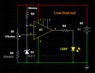
OK, here's my circuit, which uses very few components. You set your required Low Volts trigger with the R1 potentiometer, by first setting the supply voltage down to the level required, with a variable power supply. If you havn't got one, you could knock one up fairly simply & quickly.
Current consumption in standby mode with a LT1077 for eg = 840uA ! MicroPower OpAmp http://www.linear.com/docs/2472
Current consumption in the triggered mode = plus the LED current.
Flashing LED's, usually need 10's of mA. But you should be able to reduce it to say 5mA - 10mA via R4. For 5mA it would be 520ohms. As this should not be for a prolonged period, i don't see it as an issue really. For eg, http://www.rapidonline.com/pdf/55-1210.PDF
Any questions etc, fire away.
All the best with it
Attachments
@Zero D
Darn! I was hoping to preempt your message... staying with the KISS principle it occurred to me that one way to control battery depletion, and make sure than the battery check doesn't create pops and clicks in the recording audio, is to make the battery check a manual process that I can call up between takes.
And since I don't have to worry about long-term battery consumption, I can use a simple small 10-LED bar and a LM3914 to drive them. With some experience, a bargraph will help me predict the battery status and behavior much better than a single LED ever could.
So thanks anyways for the circuit, Zero G. Might be useful down the road for something else.
I'll draw complete plans for this project this weekend and post them here.
It's going to be a few more days till I post a schematic (still working out details), but in the meantime I found a cheap battery check solution from EIModule.com. For about $11 USD including shipping from England, you can get a voltage readout from 3-32v, with 3 digits, powered from the battery under test. There's actually different kits available; I chose the BLUE,DC3.0~30V) (EIM383-B) which seems to have protection diodes and is their most recent module (you have to look around)
They also had a LM3914 based one with a nice green/yellow/red readout, but for some reason it's gone today. Anyway, I figure it's better to get a clear numerical readout.
FYI...
They also had a LM3914 based one with a nice green/yellow/red readout, but for some reason it's gone today. Anyway, I figure it's better to get a clear numerical readout.
FYI...
Yes, a 3 digit powered from the battery under test sounds nice, especially @ that $ ! However, unless you are going to continually check the V, as i doubt you'll leave it connected full time, you won't get an instant alert of your desired low V point ! With the flasher circuit you would
- Status
- This old topic is closed. If you want to reopen this topic, contact a moderator using the "Report Post" button.
- Home
- Source & Line
- Analog Line Level
- A Targeted Preamp for Unbalancing and Phantom Powering