I haven't measured the output current yet but is quite high.
I got nailed by it a few times and it didn't exactly tickle !!!
The input current is about 3.5 amps (3.8 amps max shorted) or so at 14v to 18v while it is drawing an arc continuously.
jer")
Ouch... did the charged caps get you?
I always run a grounded probe through all the connections before touching anything.
Here are a couple of threads that may be of interest to you,
http://www.diyaudio.com/forums/planars-exotics/72967-esl-headphone-direct-drive.html#post831791
and,
http://www.diyaudio.com/forums/head...discrete-class-headphone-amp.html#post2596223
This is the beginning to the previous link,
http://www.diyaudio.com/forums/head...discrete-class-headphone-amp.html#post2589794
I never went any farther than about 200v as I had other things that I had to do first.
But I did prove the concept by stacking about 4 or 5 FET's.
And I drove a Piezo element with two circuits in push pull.
It was quite loud and clean and I thought the element was going to crack but it didn't !!!
I have such circuits already drawn up and simulated in Circuitmaker for the 3KV to 5Kv range, But I just haven't got the parts to try them yet.
LTspice would be a good place to start for designing such a circuit as the whole stack could short and blow up losing a whole bunch of parts if not all of them in one instant.
All it would take is for one to go bad for a domino effect to occur.
I started at a lower voltage until I got the voltages stages balanced and equal then I brought the supply up another step and rechecked and adjusted everything until I got to 175v (160v to 180v).
My supply consisted of the same 25.2v radio shack transformer that I used to power my variable bias supply with a diode multiplier of 4 to 6 stages.
I don't remember exactly how many as it was about 5 years ago when I did it.
This was before I learned how constant current sources worked that is necessary in order to eliminate the costly power resistors by using FET's instead.
The use of load resistors is fine providing the current is low.
I have another schematic that I got from another forum that is along the lines of what you are trying to do and it uses a bunch of ZTX458's and ZTX558's stacked up and driven from a opamp on a +/- 800v supply and could be expanded very easily for higher voltages as well.
If it works as I would like to try it myself.
I will search for the JPEG and post it for you.
jer
Thanks for the links!
I always thought those piezo elements work at low voltages....
Yeah, I see the domino effect too.
I'm using my transistors at 60% of rated voltage.
Wait... Aren't FETs more expensive then the resistor??
you can not run your corona through zero volts, because it will extinguish. assuming that you are not making the corona with an DC or AC voltage as a bias... in which case what you want looks like a modulator for RF.
_-_-bear
EDIT: See post below.
Last edited:
Here is that schematic that I promised.
I have not simulated it yet so I don't know if there are any error's.
jer
What was your amp intended to drive?
It seems that your design would produce an output swing about 0V.
Mine swings about 2500V (Relative to Gnd, 5500V relative to HV- ) with a full swing of +/- 450V.
The 5500Vdc is to create the corona discharge.
How would you explain plasmasonic headphones to a beginner?
You use very high currents to make plasma in the headphones that oscillate in certain frequencies? Sounds like total madness and nothing I'd wear on my head
Seems like a cool project, but don't kill yourself in the process!
You use very high currents to make plasma in the headphones that oscillate in certain frequencies? Sounds like total madness and nothing I'd wear on my head
Seems like a cool project, but don't kill yourself in the process!
How would you explain plasmasonic headphones to a beginner?
You use very high currents to make plasma in the headphones that oscillate in certain frequencies? Sounds like total madness and nothing I'd wear on my head
Seems like a cool project, but don't kill yourself in the process!
Well, there are many types of "plasma" headphones.
The one I'm making doesn't actually consist of matter in the plasma phase (as you mention) because that's WAY too dangerous (more than it already is). The ones you're talking about are used as speakers (tweeters).
Mine uses an effect called "Corona discharge" which doesn't get very hot and dissipates much less power compared to the plasma glow discharge.
The the Corona discharge will create something called Ionic (Corona) Wind. By modulating the amount of wind (air flow), it creates sound.
Yes, The charged caps got me at around 8.5kv.
I was adjusting the position of my little panel ESL and wasn't watching as I was removing my hand from the panel and I brushed the wire feeding the diagphram.
When the supply detects a voltage drop it instantly ramps up to compensate for it as it will produces13.8kv !!!
This is why I keep one hand in my pocket when messing with such high voltages.
The charge flowed down the side of my body instead of across my chest, Actually I was quite lucky !!!
"I always thought those piezo elements work at low voltages...."
Yes, That is why I was surprised that it didn't shatter on me!!
"Wait... Aren't FETs more expensive then the resistor??"
It depends on how much current is running through the stack of transistors.
The resistor acts as a constant current source and a 40 watt transistor is much much cheaper than a 40 watt resistor.
Let alone a circuit designed for a much higher wattage's and currents.
The amp design is a Single Ended Class A Push Pull Design.
It is intended to directly drive ESL transducers and the voltages are selected to fit the panel it is driving.
Each leg will swing from 0v to the supply voltage Therefore the outputs are 180 degrees out of phase and the peak to peak output voltage swing is twice that of the power supply like a bridged amplifier (BTL) would do.
An ESL headphone driver only needs about 500v to 1000v in order to operate with very good performance.
Where as a larger panel requires in excess of 2.5kv to 5kv and more to really start performing well.
A lot of this depends on the size of the panel its D/S (diagphram to stator spacing) and coating materials.
I was pushing a 6Kv and 8.5Kv bias and about 25Kv P-P on the stators when my stator coating failed and my little panel burst into flames, as this did happen twice and ruined one of them.
The output is taken at the junction of the top resistor and the stack of transistors and is biased so that this point is at half of the supply voltage.
The value of the resistor determines how much current is going to flow through the stack, Hence a constant current source.
There are some very large samples of this type of design buried deep in these threads and some low power versions for headphones at the Headwise website as well.
A complete description of some tube based designs can be found at Roger Sanders white pages at his website as well as Broskies Tube Cad Pages.
As I have mentioned the amp project was put on hold until I determine exactly the voltage range that I will need in order for the panels to perform well and reliably at maximum safely, and, without burning up!
jer
Last edited:
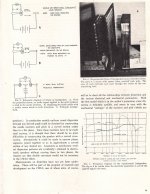
I just found this document in the 4hv.org forum I have not tried to find the rest of it yet.
I had done a little researching on this subject awhile back about 14 years ago while I was beginning to learn and find stuff on ESL's and plasma speakers and I remember seeing this before.
Enjoy !!!
jer
P.S. Here is the link to the complete article in PDF,
http://www.airspeaker.co.uk/JAES 1957.pdf
I had done a little researching on this subject awhile back about 14 years ago while I was beginning to learn and find stuff on ESL's and plasma speakers and I remember seeing this before.
Enjoy !!!
jer
P.S. Here is the link to the complete article in PDF,
http://www.airspeaker.co.uk/JAES 1957.pdf
Attachments
Last edited:
- Status
- This old topic is closed. If you want to reopen this topic, contact a moderator using the "Report Post" button.
- Home
- Loudspeakers
- Planars & Exotics
- A Student's Attempt at the Plasmasonic Headphones.