Re: Re: A simple active DC dummy load for PSU testing
I in for it!! looks very easy like that. Email me or post here, thanks! How much power, say short term, few seconds can hold up? As much as transistor does?lineup said:
If anyone is interested, I post my schematic used, in real life application.
Works like a charm
Useful? Yes!!!
Difficult to build? No!!!
I have not designed it for any higher power.
It was more for just see how much the VDC would be for a lower normal current.
I was working with preamplifiers / headphone amplifiers transformers at the time.
Like 10 - 20 -30 VA, like.
But of course same circuit can be altered for any power.
= Bigger heatsink
= More powerful transistor.
= And upgrade my current set resistors.
= From 1 Watt Metallfilm units, to real power resistors 5W / 10 W
Now I may have to search for a couple of days after my schematic.
I only did write it down on piece of paper.
Where I also did the MATH to set all things right.
The circuit is of course supplied by the LOAD.
But I did manage to get consumption down to like 1 mA.
So when we measure current output, we only get an error of 1 mA.
Hehe.
If I am lucky I would scan my room ( I have only 1 room to live in )
and remember quite closely where I have those old documents.
If not lucky, I promise I will re-draw my circuit .. from memory and from studying my device
= backengineering myself.
And then make a new and better circuit!
Because I know a lot more today, then what I did 1995 ( 12 years ago ).
I have posted well over 3.000 posts in this forum.
Using these 3 Moinkers:
1. gromanswe
2. halojoy
3. lineup
... this is my diyaudio.com story")
If I am lucky I would scan my room ( I have only 1 room to live in )
and remember quite closely where I have those old documents.
If not lucky, I promise I will re-draw my circuit .. from memory and from studying my device
= backengineering myself.
And then make a new and better circuit!
Because I know a lot more today, then what I did 1995 ( 12 years ago ).
I have posted well over 3.000 posts in this forum.
Using these 3 Moinkers:
1. gromanswe
2. halojoy
3. lineup
... this is my diyaudio.com story
Okay.
I make 2 versions.
1. The old .. from studying my device. With everything same.
2. A new one. with some slight improvements.
Now, luka.
We must not forget, that bootstrapper has posted a great circuit in post #1.
This one has features that my circuit doesn't have.
Like a central 0 Volt terminal.
This means you can measure both windings ( + and 0 and - ) of your power supply independantly.
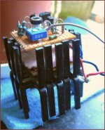
If you study this picture I took 20 minutes ago,
you see my circuit has got 3 connections = 3 wires.
Those 2 in bottom right, are those you connect to transformer.
this is the both legs of this active resistor.
> red = V+ from rectifier bridge
> blue = V- from rectifier bridge
> grey = the upper little wire, to measure the current across 1 Ohm resistor
1 Volt between blue/grey = 1 Ampere
0.5 Volt from = 500 mA
Actuially I remember now, that 0.5 Ampere is the max current I dared to pass.
Now if we know Voltage between V+ and V- and the current
we can get this resistor value:
Volt / Current = Ohm
Here is my fresh photo, showing these 3 wires.
I make 2 versions.
1. The old .. from studying my device. With everything same.
2. A new one. with some slight improvements.
Now, luka.
We must not forget, that bootstrapper has posted a great circuit in post #1.
This one has features that my circuit doesn't have.
Like a central 0 Volt terminal.
This means you can measure both windings ( + and 0 and - ) of your power supply independantly.
If you study this picture I took 20 minutes ago,
you see my circuit has got 3 connections = 3 wires.
Those 2 in bottom right, are those you connect to transformer.
this is the both legs of this active resistor.
> red = V+ from rectifier bridge
> blue = V- from rectifier bridge
> grey = the upper little wire, to measure the current across 1 Ohm resistor
1 Volt between blue/grey = 1 Ampere
0.5 Volt from = 500 mA
Actuially I remember now, that 0.5 Ampere is the max current I dared to pass.
Now if we know Voltage between V+ and V- and the current
we can get this resistor value:
Volt / Current = Ohm
Here is my fresh photo, showing these 3 wires.
Attachments
I'm interested in yours, because is looks similar to what I'e found some time ago and would compare them
Here is one
http://84.255.231.51:81/doc/High Power Adjustable Load.pdf
and other
http://electronicdesign.com/Articles/ArticleID/3239/3239.html
Here is one
http://84.255.231.51:81/doc/High Power Adjustable Load.pdf
and other
http://electronicdesign.com/Articles/ArticleID/3239/3239.html
That second link
shows very simple circuit.
It is using a wellknown Op-Amp called LM10.
Which has a built in Voltage Reference = 0.2 V
The concept is 100% same as mine, basically.
Also this is powered from the attached Power Supply = trafo.
shows very simple circuit.
It is using a wellknown Op-Amp called LM10.
Which has a built in Voltage Reference = 0.2 V
The concept is 100% same as mine, basically.
Also this is powered from the attached Power Supply = trafo.
An externally hosted image should be here but it was not working when we last tested it.
Yes, it has two basic modes.
As a constant current source load and as a constant resistance load.
It is upto anyone what one think one need.
For me it is enough to have an adjustable and constant resistance load.
Because I only use my unit for testing new transformers.
To see what Voltage DC output will be like with some loading.
Some time ago i builded something simular to a regulated load .
Since i only used it in prototyping fase there is no problem posting it here .
Let me start from the beginning .
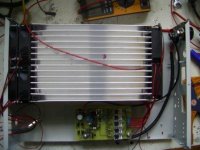
This module is a test setup i builded as part of a battery charger / discharger for the Nickel battery of a tram .
There are 2 versions first just discharges at the rate you set with the duty cycle potentiometer the second is current stabilised .
As i builded it with 42 Volt @ 20 Amperes it functions at about 52 Celcius .
You could smoothen it a little by adding capacitors .
It is very straight forward i guess (although its a little bit of abuse of parts)
Termistor (r20) or shutdown line (5 volt from microcontroller) can shut the pwm down through the shutdown pin.
The rest speaks for itself i guess ,most of you will know about the SG3525
The second version differs only in a sort of *feedback* the first version the current dropped with the voltage the second makes the duty cycle rise when the voltage drops stabilising the current .
You can easily make some changes or upscale c.q. downscale if you like .
In the zip file you will find a multisim schema (no simulation) ,
2 pcb's made in proteus and a picture of the module as i builded it .
Do keep in mind the pwm is not filtered .
For smoothening you will have to add capacitors or calculate a filter according to the frequency you set .
The design itself turned out to be very robust .
Even uncooled the mosfets are no more then handwarm (also reversed polarity proof) (i used irf1405)
I never had any destroyed parts in this setup while the test supply was upto 50 volt 25 Ampere .
(Be carefull soldering the mosfets cause there is little space between the leggs)
http://rapidshare.com/files/133893583/pwmload.zip
Good luck
Since i only used it in prototyping fase there is no problem posting it here .
Let me start from the beginning .
This module is a test setup i builded as part of a battery charger / discharger for the Nickel battery of a tram .
There are 2 versions first just discharges at the rate you set with the duty cycle potentiometer the second is current stabilised .
As i builded it with 42 Volt @ 20 Amperes it functions at about 52 Celcius .
You could smoothen it a little by adding capacitors .
It is very straight forward i guess (although its a little bit of abuse of parts)
Termistor (r20) or shutdown line (5 volt from microcontroller) can shut the pwm down through the shutdown pin.
The rest speaks for itself i guess ,most of you will know about the SG3525
The second version differs only in a sort of *feedback* the first version the current dropped with the voltage the second makes the duty cycle rise when the voltage drops stabilising the current .
You can easily make some changes or upscale c.q. downscale if you like .
In the zip file you will find a multisim schema (no simulation) ,
2 pcb's made in proteus and a picture of the module as i builded it .
Do keep in mind the pwm is not filtered .
For smoothening you will have to add capacitors or calculate a filter according to the frequency you set .
The design itself turned out to be very robust .
Even uncooled the mosfets are no more then handwarm (also reversed polarity proof) (i used irf1405)
I never had any destroyed parts in this setup while the test supply was upto 50 volt 25 Ampere .
(Be carefull soldering the mosfets cause there is little space between the leggs)
http://rapidshare.com/files/133893583/pwmload.zip
Good luck
Attachments
The semiconductor version is only usable for small powers .
If you want it to be reliable you will have to use resistors & mosfet .
For testing on high power like i had to do with the trams or chargers upto 2 KW using the I2R of a mosfet is almost impossible .
To do that with lightbulbs (which we did at times) its to much work .
This was maybe a bit more work but its sure beats garbage cans of water with resistors + 30 halogens for testing a 150 Ampere charger .
With a microcontroller you can easily make a nice resistive pwm load .
(the final versions i made are based on microcontroller)
Same setup just the pwm & ventilator control are done by MCU .
For powers of a Kilowatt or more only semiconductors is no option i'm afraid .
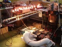
@Dmfraser.
You mean something simple like this ?
(Victim under test is a 13.8 Volt - 133 Ampere lead acid charger)
This is why i chosen to put a little more effort into it .
Just hook it up set the current wanted and let's roll.
(is nice in winter too to warm your feet)
You mean something simple like this ?
(Victim under test is a 13.8 Volt - 133 Ampere lead acid charger)
This is why i chosen to put a little more effort into it .
Just hook it up set the current wanted and let's roll.
(is nice in winter too to warm your feet)
Attachments
Hi,
here's my latest concept:
Active DC load
The general idea hasn't changed much. Now I added the zener diode to lift the voltage levels enough for the op amp. Also there are individual gate resistors as well as current sensing for each FET. Not all the component values are final, but at least somewhat so. I have several IRFP460s lying around so that's why they will be used.
The resistors R5 & R12 should be chosen in a way that the Vref voltage is as close to zero as possible (or even slightly below zero) when the pots are set to minimum. This is required since the pots will have a certain non-zero minimum resistance and this leads to small amount of current that will be drawn from the test supply.
One can perform step loading test if Vref is supplied from a function generator via BNC connector. Before this can be done, the required step voltage must be carefully chosen.
Thoughts on this one?
What kind of oscillation do you mean? The circuit diagram isn't complete yet, there will be small caps at the test voltage input and also op amp decoupling. I haven't taken FET oscillation into account yet, but I guess that small 2.2nF cap helps a bit with the gate drive. This is an issue I really have to think about, thanks for reminding!
- Status
- This old topic is closed. If you want to reopen this topic, contact a moderator using the "Report Post" button.
- Home
- Amplifiers
- Power Supplies
- A simple active DC dummy load for PSU testing