SmarmyDog said:Sorry, I thought we were joking around...
4fun: Shaded area = energy. Shaded areas per second = power.
Yes I know that
")
Good that you pointed it out.
I just throw that it in for that quarter power theory......
Doh!
My sincere apologies to Mr. jneutron.
The power is halved, not quartered.
What really threw me was this:
And a lot of people saying "the voltage is halved".*
Rest assured, if the RMS voltage were halved, the power would be quartered. However, the RMS voltage is not halved, it is reduced by a factor of 1/SQRT(2), and therefore the power is halved.
I think that something is wrong with Carlos' multimeter. Why did it tell him that half wave rectified 120 VAC is 60 V RMS?
edit:
* hmmm... I think even that might be a figment of my own imagination. Oh dear, it isn't going well today. Maybe it's got something to do with it being 02:20.
I'd still like to know what's wrong with Carlos' multimeter.
My sincere apologies to Mr. jneutron.
The power is halved, not quartered.
What really threw me was this:
refference said:Hi vax9000 , Hi all ,
The RMS value of a half-wave rectified 120 VAC ( RMS )
is 60 V RMS ( measured with a true RMS multimeter ) .
And a lot of people saying "the voltage is halved".*
Rest assured, if the RMS voltage were halved, the power would be quartered. However, the RMS voltage is not halved, it is reduced by a factor of 1/SQRT(2), and therefore the power is halved.
I think that something is wrong with Carlos' multimeter. Why did it tell him that half wave rectified 120 VAC is 60 V RMS?
edit:
* hmmm... I think even that might be a figment of my own imagination. Oh dear, it isn't going well today. Maybe it's got something to do with it being 02:20.
I'd still like to know what's wrong with Carlos' multimeter.
You know,
This is getting downright silly. I was going to work through the math on this, just for giggles, until I realized the math would be based on: ENERGY in a HALF-CYCLE...
Full wave energy, over the course of one second, can be divided into 120 packets... it doesn't get much simpler.
If you don't get 25 Watts, do some homework, and tell us all that you NOT working on airplanes, ships, trains, bridges, or my pacemaker.


Sorry Harry... cross posted.
This is getting downright silly. I was going to work through the math on this, just for giggles, until I realized the math would be based on: ENERGY in a HALF-CYCLE...
Full wave energy, over the course of one second, can be divided into 120 packets... it doesn't get much simpler.
If you don't get 25 Watts, do some homework, and tell us all that you NOT working on airplanes, ships, trains, bridges, or my pacemaker.
Sorry Harry... cross posted.
Hi HarryDymond ,
NOTHING WRONG with my DMM , because it’s a FLUKE
TRUE RMS MULTIMETER model 45 ( bench top ) ,
5 ½ digits .
If you have a high-quality DMM like this , try to measure
the TRUE RMS voltage , after half-rectified , at the input
of a 50 Watts iron solder , before contest my measure .
When we are talking about AC voltage , the ONLY value
that has any interest is the RMS value , because is it that
execute the job .
My answer to the quiz , is 12.5 Watts , yet .
Regards ,
Carlos
Carlos,
You are only measuring AC component and not DC+AC component combined.
After all we have as result a pulsating DC after diode.
Measure also DC then take:
TRMS=sqrt(AC^2+DC^2)
Fluke 45 can be setup to do it according to page 45 in english manual.
I have this multimeter myself, nice instrument.
You are only measuring AC component and not DC+AC component combined.
After all we have as result a pulsating DC after diode.
Measure also DC then take:
TRMS=sqrt(AC^2+DC^2)
Fluke 45 can be setup to do it according to page 45 in english manual.
I have this multimeter myself, nice instrument.
Hi poobah ,
No needs to repair my DMM , it’s working properly .
Hi 4fun ,
You are correct , FLUKE is a amazing test equipment .
May be the best one !!! ???
Poobah and 4fun ,
Everything posted on this thread , looks like a big joke
( specially the posts # 12 by jane , # 21 by jneutron ,
# 22 by poobah , # 29 by KBK , # 30 by digitaljunkie and
the BEST POST # 36 by smarmydoq )
So , my only intention , was to start a little polemic contro-
versy , about the correct answer .
After all that I said above , I’ll give the correct and final
answer :
The correct answer is ............ 12.488888888 ,
then aprox. 12.5 Watts
Regards for all ,
Carlos
P.S. Where are Vax 9000 ???? The thread starter
The load has been declared resistive, therefore current and voltage are in phase. There are 120 points in time, during a 1 second period, when voltage, current, and therefore power are all zero.
Thus, there are 120 packets of energy delivered per second.
50 Watts = 50 Joules per second
50 Joules / 120 packets = 0.4167 Joules per packet
If we remove every other packet, we will have 60.
60 packets per second times 0.4167... Joules per packet = 25 Joules per second,
equals 25 watts
Thus, there are 120 packets of energy delivered per second.
50 Watts = 50 Joules per second
50 Joules / 120 packets = 0.4167 Joules per packet
If we remove every other packet, we will have 60.
60 packets per second times 0.4167... Joules per packet = 25 Joules per second,
equals 25 watts
Do it the practical way if you prefer:
Take a (say) 100W lamp, and put the diode in series with it.
Estimate the light output: is is equivalent to a 50W or a 25W lamp?
(Undoubtedly, it's 50W).
QED
In fact you could do the same thing properly, using your iron and heating a known volume of water. The output of the iron is then easily calculated. If (as I'm sure it will) it puts out 25W - less a bit for losses - and (as contended) consumes only 12.5, file that patent quickly!
A further 'thought experimental' solution:
Connect a pair of parallel diodes back-to-back in series with the iron. AC is now restored. If each diode is supplying the current for 12.5W, where's the other 25W coming from?
You have to solder the diode onto the wire before cutting it, of course
I had a similar problem when I owned only one (Antex) iron. The element had soldered terminals, which was fine until it needed replacing...
Connect a pair of parallel diodes back-to-back in series with the iron. AC is now restored. If each diode is supplying the current for 12.5W, where's the other 25W coming from?
I'm still having trouble soldering the diode in series with the AC line -- the soldering iron stops working when I cut the wire to splice-in the diode. What am I doing wrong?
You have to solder the diode onto the wire before cutting it, of course
I had a similar problem when I owned only one (Antex) iron. The element had soldered terminals, which was fine until it needed replacing...
Carlos,
I was wrong about page 45 in manual, page 57-58 is correct regarding PDF manual.
You will find it here:
http://assets.fluke.com/manuals/45______umeng0400.pdf
It will tell how to set up Fluke 45 correctly for this purpose, altogether with curvforms and everything.
Did you measure according to my previous post, #48?
And...Please tell us that you will get 25W after reading manual.
I had a similar problem when I owned only one (Antex) iron. The element had soldered terminals, which was fine until it needed replacing...
I used to play a mean prank in the shop sometimes. When people were done using the solder pot, they would naturally unplug it. When no one was looking I would take the plug for the solder pot and hang it with prongs immersed in the cooling solder -

refference said:Hi HarryDymond ,
NOTHING WRONG with my DMM , because it’s a FLUKE
TRUE RMS MULTIMETER model 45 ( bench top ) ,
5 ½ digits .
If you have a high-quality DMM like this , try to measure
the TRUE RMS voltage , after half-rectified , at the input
of a 50 Watts iron solder , before contest my measure .
When we are talking about AC voltage , the ONLY value
that has any interest is the RMS value , because is it that
execute the job .
My answer to the quiz , is 12.5 Watts , yet .
Regards ,
Carlos
Most multimeters are calibrated for RMS value of a sine wave. Clip half of it, or use a squarewave with the same amplitude, and all indications become wild guesses. It takes a pretty sophisticated mm to actually calculate the RMS for different wave forms to be correct with different so called "crest factors" which is the ratio of peak voltage to RMS. As an example, music has very high crest factors: very low RMS but relatively high peaks. So, a peak rectifier meter calibrated in RMS will indicte way too high.
Anyway, I digres. The point is that most mm are calibrated and designed with sinewaves in mind. If you have a cheap mm, that uses internal single rectification and indicates the peak value, calibrated in RMS, you wouldn't see any difference if you clip one side of the input sine. Or, depending on the polarity, your indication goes to zero if you clip the wrong polarity.
Jan Didden
Correctamundo, Jan.janneman said:
Most multimeters are calibrated for RMS value of a sine wave. Clip half of it, or use a squarewave with the same amplitude, and all indications become wild guesses. It takes a pretty sophisticated mm to actually calculate the RMS for different wave forms to be correct with different so called "crest factors" which is the ratio of peak voltage to RMS. As an example, music has very high crest factors: very low RMS but relatively high peaks. So, a peak rectifier meter calibrated in RMS will indicte way too high.
Jan Didden
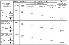
Carlos:
Here's the relevant part of the figure 4.3 from the fluke manual that shows how this meter reads various signals.
Examine the table closely. It says that for a true rms reading of 1 volt, you put in either a 1.4 volt (0 to pk) full sine, that same 1.4 volt sine but full wave rectified, or....a 2 volt peak half wave rectified sine..
What you are doing the equivalent of, is putting in a 1.4 volt half wave sine. So you are providing only ~70% of the equivalent voltage to give the 1 volt reading as per fluke's table. The meter will read 70.17% of the actual waveform.
Care must be taken when trying to interpret the readings.
As I stated, by inspection the answer is half power. Poobah has also calculated correctly on a lobe by lobe basis.
Cheers, John
Attachments
- Status
- This old topic is closed. If you want to reopen this topic, contact a moderator using the "Report Post" button.
- Home
- Amplifiers
- Tubes / Valves
- a quiz about AC power