Things to ponder...
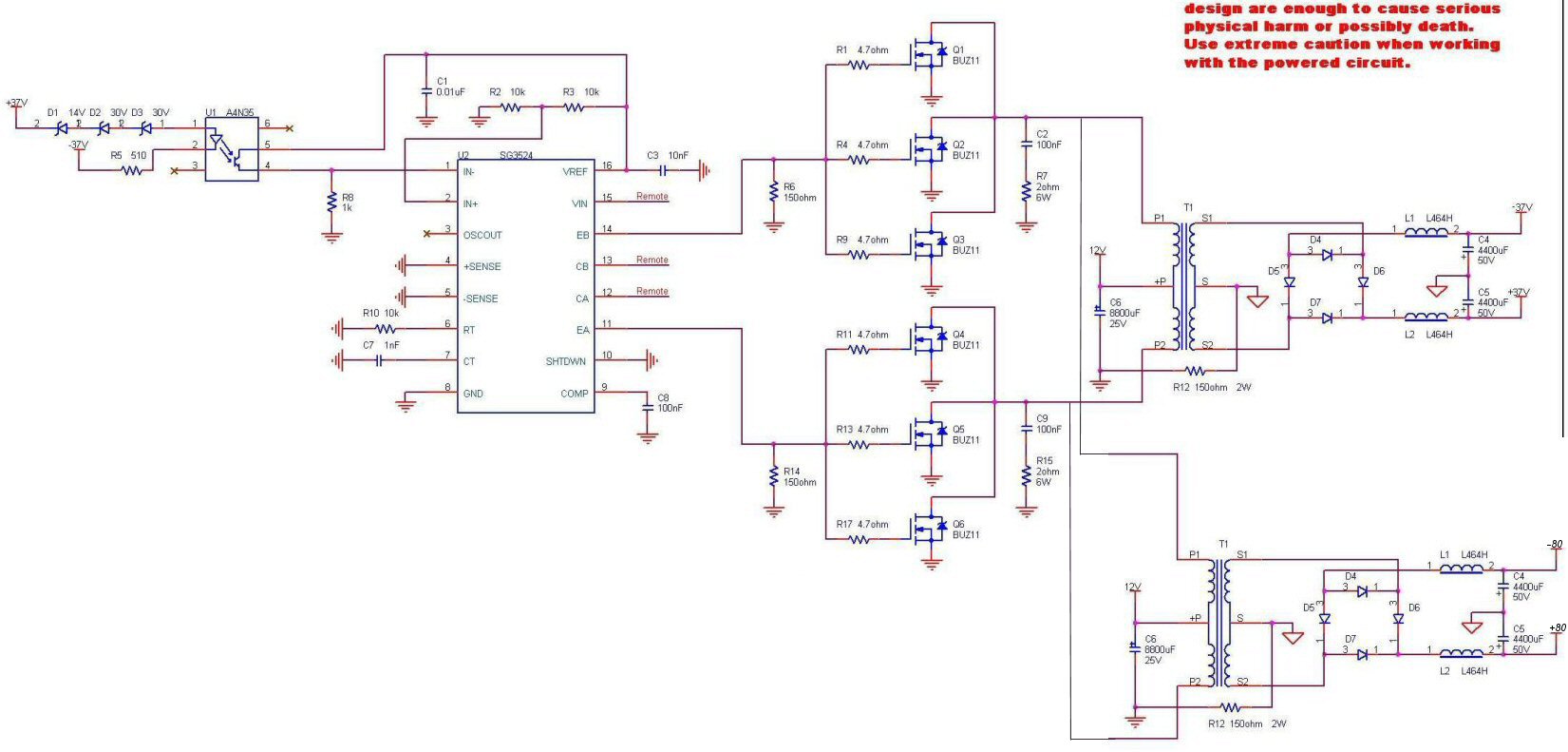
What's R12's purpose? Its commonplace to tie the secondary CT to ground.
Given the output is significantly higher than what you were expecting, it sounds like the turns ratio is off a bit.
If the output isn't symmetrical with respect to the CT, are you sure it's really in the center? If so, it sounds like you don't have a good square waveform. I suppose a crippled rectifier could also cause asymmetricality, but certainly it would overheat to cause that much difference. Are the diodes fast enough to work at your switching frequency?
I don't know much about PWM controllers, but that looks like a heavy load for it to drive directly. Is the SG3524 capable of that much current?
Have you tried the circuit without regulation?
The big question: do you have a 'scope to snoop around with?
Tim
")
- Status
- This old topic is closed. If you want to reopen this topic, contact a moderator using the "Report Post" button.