Hi All!
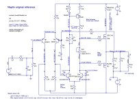
Following the interesting discussion in Sevy's sizzling amplifier thread, which has many frequency plots to determine stability, I decided to use LTspice to look at my own mods on the Maplin amp.
I understand that when the GNFB becomes positive above 0dB gain, it's an oscillator, but just by looking at the output I was way beyond that with lots of gain...
Also then any mods increasing that gain, changes the game, and I think the little capacitors over TR3 and TR4 move the poles (haven't investigated that yet). I think Douglas Self referrs to the one on TR3 as 'Cdom', which I think is the on controlling the dominant pole, or it's just much bigger than the varying transistor parasitic, so it dominates it with a nice external fixed value capacitor.
I wasn't understanding much, as it still had a big gain at 180 degrees... but I know it works well..
... so I then looked at the original amplifier design, as I know that's stable (subject to slight scorching of the output snubber (the emergency brake?) - common on a few of these PCBs...), and found myself asking:
1. What's that bump at 800MHz?
2. Why doesn't this design oscillate?
Eventually I decided to measure the phase margin in a slightly unusual way.. that of each side of the LTP, specifically the bases of each transistor, TR1 and TR2. I figure that this is the actual, important bit, so the phase margin between each side was really the bit that decided it if was an amplifier or a bell, or an oscillator...
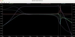
Doing this, created the (rather pretty) attached graph, which has a mild phase shift (so it's an amplifier), but I still have this awkward question..
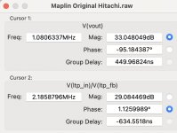
Plotting LPT+ / LTP-, see the red curve, V(ltp_fb) / Vltp_in), well, I've never heard of that, but it seems logical - that's the 'brain', so the question is, 'am I doing it right'?, and 'what else do I need to know'?
This is then allied to the questions of 'should this peak be around 2.2MHz'?
I think that's one of the poles, not sure about zeros. I know what they are but I could learn more")
So could people please have a look and comment? It would be most helpful, thanks!
Following the interesting discussion in Sevy's sizzling amplifier thread, which has many frequency plots to determine stability, I decided to use LTspice to look at my own mods on the Maplin amp.
I understand that when the GNFB becomes positive above 0dB gain, it's an oscillator, but just by looking at the output I was way beyond that with lots of gain...
Also then any mods increasing that gain, changes the game, and I think the little capacitors over TR3 and TR4 move the poles (haven't investigated that yet). I think Douglas Self referrs to the one on TR3 as 'Cdom', which I think is the on controlling the dominant pole, or it's just much bigger than the varying transistor parasitic, so it dominates it with a nice external fixed value capacitor.
I wasn't understanding much, as it still had a big gain at 180 degrees... but I know it works well..
... so I then looked at the original amplifier design, as I know that's stable (subject to slight scorching of the output snubber (the emergency brake?) - common on a few of these PCBs...), and found myself asking:
1. What's that bump at 800MHz?
2. Why doesn't this design oscillate?
Eventually I decided to measure the phase margin in a slightly unusual way.. that of each side of the LTP, specifically the bases of each transistor, TR1 and TR2. I figure that this is the actual, important bit, so the phase margin between each side was really the bit that decided it if was an amplifier or a bell, or an oscillator...
Doing this, created the (rather pretty) attached graph, which has a mild phase shift (so it's an amplifier), but I still have this awkward question..
Plotting LPT+ / LTP-, see the red curve, V(ltp_fb) / Vltp_in), well, I've never heard of that, but it seems logical - that's the 'brain', so the question is, 'am I doing it right'?, and 'what else do I need to know'?
This is then allied to the questions of 'should this peak be around 2.2MHz'?
I think that's one of the poles, not sure about zeros. I know what they are but I could learn more
So could people please have a look and comment? It would be most helpful, thanks!
Attachments
Phase and gain margins pertain to the open loop response, not closed loop. To get that break the loop at the inverting input to the input pair (T2 base) and measure the response of the signal that would have gone to the input pair, while grounding the inverting input of the pair at AC. Only applies to ac analysis naturally!
I do this with an LC circuit in the feedback, set to 1GH and 1GF for open loop, 1pH and 1pF for closed loop, so its easier to switch between open and closed loop.
So for instance I have a modest-gain output section with this closed-loop response:

But the open loop response is:

Note the much higher gain of open loop, and the way it slopes down from within the audio band already, typical of any audio amp in fact. There is clearly 50 degrees or so of phase margin, maybe 12dB of gain margin (sorry it ran off the graph!).
Closing the loop shifts all the poles and zeroes around...
I do this with an LC circuit in the feedback, set to 1GH and 1GF for open loop, 1pH and 1pF for closed loop, so its easier to switch between open and closed loop.
So for instance I have a modest-gain output section with this closed-loop response:
But the open loop response is:
Note the much higher gain of open loop, and the way it slopes down from within the audio band already, typical of any audio amp in fact. There is clearly 50 degrees or so of phase margin, maybe 12dB of gain margin (sorry it ran off the graph!).
Closing the loop shifts all the poles and zeroes around...
Only the poles, actually.
Not necessarily. The phase shift has to be small enough at the point where the loop gain passes through unity (0 dB), but there can be more phase shift where the loop gain is still above 0 dB, as long as the phase comes back before the 0 dB line is crossed. Look up the Nyquist stability criterium for details.
I understand that when the GNFB becomes positive above 0dB gain, it's an oscillator,
Not necessarily. The phase shift has to be small enough at the point where the loop gain passes through unity (0 dB), but there can be more phase shift where the loop gain is still above 0 dB, as long as the phase comes back before the 0 dB line is crossed. Look up the Nyquist stability criterium for details.
BTW the circuit I mention above is this one: https://www.diyaudio.com/community/...gain-for-better-headroom.408598/#post-7651563
Also pertinent might be this posting where I manage to create Nyquist plots from LTSpice using a Python script for a particularly devious circuit: https://www.diyaudio.com/community/threads/nic-opamp-vas-topology.348646/page-2#post-6810871
[ and yes, sorry, just the poles ]
Also pertinent might be this posting where I manage to create Nyquist plots from LTSpice using a Python script for a particularly devious circuit: https://www.diyaudio.com/community/threads/nic-opamp-vas-topology.348646/page-2#post-6810871
[ and yes, sorry, just the poles ]
Last edited:
Thanks, yes I see, find the frequency where the OL gain reduces to 0dB (<= 1) and look at the phase shift, it's about 130, which gives a margin of 180-130 = 50 degrees.There is clearly 50 degrees or so of phase margin, maybe 12dB of gain margin (sorry it ran off the graph!).