I believe that you could use two LDRs anywhere you use a potentiometer, as long as the impedances match up OK.
If you use two LDRs as the two portions of a pot with a total resistance of 25K, it should work fine. The challenge is to control the LDRs in such a way that it works that way -- with one LDR decreasing resistance as the other increases, and keeping the total resistance at 25K. Also, the minimum resistance of an LDR is about 40 ohms, so you can't go to maximum or minimum, but if the total is 25K, missing out on the 40 ohms at top and bottom should be no problem.
If you use two LDRs as the two portions of a pot with a total resistance of 25K, it should work fine. The challenge is to control the LDRs in such a way that it works that way -- with one LDR decreasing resistance as the other increases, and keeping the total resistance at 25K. Also, the minimum resistance of an LDR is about 40 ohms, so you can't go to maximum or minimum, but if the total is 25K, missing out on the 40 ohms at top and bottom should be no problem.
I believe that you could use two LDRs anywhere you use a potentiometer, as long as the impedances match up OK.
If you use two LDRs as the two portions of a pot with a total resistance of 25K, it should work fine. The challenge is to control the LDRs in such a way that it works that way -- with one LDR decreasing resistance as the other increases, and keeping the total resistance at 25K. Also, the minimum resistance of an LDR is about 40 ohms, so you can't go to maximum or minimum, but if the total is 25K, missing out on the 40 ohms at top and bottom should be no problem.
control the Light intensity to the LDR with a pot? on a linear/log potentiometer.. 3 pins.. as you turn it pin 1 and 2 will go up and between pin 2 and 3 will go down.. vice versa?

control the Light intensity to the LDR with a pot? on a linear/log potentiometer.. 3 pins.. as you turn it pin 1 and 2 will go up and between pin 2 and 3 will go down.. vice versa?
Not as simple as that --
First, each LED will draw 20ma at full brightness, assuming you're looking for 40 ohms. That's a lot of current to put through a potentiometer. With stereo, that's 40ma total for two channels at minimum or maximum volume (though you wouldn't normally listen at those positions).
Second, the LED/LDR is not a linear device, more like a log curve response but not exactly. Somehow you need to make two non-linear devices going in opposite directions stay coordinated in order to maintain a desired attenuation curve.
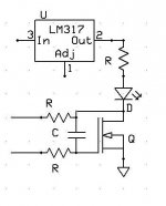
With my project, I control current with a mosfet acting as a variable resistor for each LED, and the mosfet resistance is controlled by a PIC which handles the coordination and fine tuning. The mosfet will handle much more current than a potentiometer will, and the PIC allows the 'intelligence' to carefully control how much current is applied to each device.
The difficult part is the wide range of the current involved to control the LDR resistance to deliver an appropriate attenuation range while maintaining flat Z -- from 20ma maximum to something like .005ma.
Now where did I publish that chart affirming Silonex' numbers...
That chart with the 'similar' lines was logarithmic in both current and resistance. The forecast and measured value lines looked similar, but when you start looking at the lines in terms of 'difference in ohms' or 'difference in current' from the perspective of having to correct for that difference in the real world, then the differences became seriously nontrivial regardless of how close the lines are on the graph.
Would you mind posting a schematic for this?
If by 'this' you mean my PIC-based board, I shouldn't do that yet, because the circuit is by no means final -- as I posted earlier, I made major changes as lately as a few days ago, and anyway the important part is the programming of the chip which is in it's earliest conceptual stages.
The concept is straightforward -- to use mosfets as variable resistors instead of the potentiometer as used in georgehifi's "Lightspeed" and to control the resistances with as much precision as possible using a PIC. The goal is to create a multi-channel, constant Z attenuator with closely controlled parameters in each channel without closely matched LDRs. Ideally, a single pot master volume control will be able to control the gain on as many channels as desired without audible shifting of the sound stage.
The basic building block is simple, and I'll post the schematic below. The PIC is connected to each mosfet/LDR set via a control line which goes to the gate of the mosfet and adds or removes voltage at the gate to change the mosfet transconductance, and a feedback line which reads the voltage drop across the mosfet to determine whether the gate charge is correct or needs to be raised or lowered. The PIC reads the feedback and applies correction to the gate charge. This all happens so fast that the mosfet can be held at a given level with fine precision. The controllable resistance allows control of the current through the LED, which in turn controls the resistance across the LDR.
Attachments
Ummm... maybe I won't use it in front of a preamp. Will use by itself.
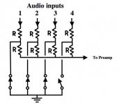
Most of the builds I see have only 1 input & 1 output. Any problem with using a switch for a couple of extra inputs? Probably not, but would like to ask away.
Thx,
Vince
The folks who esteem the LDR 'sound' say that the goal is to avoid all switches and potentiometers in the signal path. You can read about all this on the Lightspeed thread. The holy grail of pure LDR sound is thus diminished when you put a selector switch into the path.
A full LDR solution would use LDRs to switch inputs rather than a mechanical switch. An 'off' LDR has several megohms of resistance, ideal for blocking a signal, and a full 'on' LDR can be as low as 40 ohms. You would have to design your system carefully to implement an LDR selector, but I think it can be done successfully.
About a year ago I tested a bunch of Silonex LDRs. About 15 of the 25 could be considered useful. After charting them at various currents, I came up with an "average" LDR response in ohms:
30 + 3.5 x^-2 + 130x^-1
where x is current in ma. I hope this helps someone out there.
30 + 3.5 x^-2 + 130x^-1
where x is current in ma. I hope this helps someone out there.
you might want to have a look at linuxworks posts on head-fi and the aurduino fotums. he came up with this idea last year )maybe earlier, but posted about it last year.
he has a well developed aurduino project catalogue including a nice relay attenuator, an LCD controller etc etc.
should be plenty of info that will come in handy in his posts if you havent found them already.
he has a well developed aurduino project catalogue including a nice relay attenuator, an LCD controller etc etc.
should be plenty of info that will come in handy in his posts if you havent found them already.
linuxworks said:an idea I've been thinking of (way in the background) is to try some of these LDR things but have a CPU controller and a non-audio DAC (binary-to-voltage converter) drive the ldr's. the 'thing' about the ldr's, as I understand it, is that they need matching and calibrating. that's a natural thing for a CPU and some lookup tables to do! the trick is, then, to run some calibration on a completed circuit and generate the 'value tables' for the CPU to use.
in theory, that totally eliminates the matching hassles or non-linearity of the devices.
but I have yet to try this, myself. too many other projects still pending.
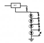
Use LDR instead of the series R and use the attached ckt to control its LEDs.
For other shunt contact, use the other contact on the relay.
All the contacts shown r of the relay that should be used to select the input.
Gajanan Phadte
Note:This idea is claimed by linuxguru(now linuxworks) to be his after it was carelessly handled by a reputed publisher. Enough of it, hahahaha.
For other shunt contact, use the other contact on the relay.
All the contacts shown r of the relay that should be used to select the input.
Gajanan Phadte
Note:This idea is claimed by linuxguru(now linuxworks) to be his after it was carelessly handled by a reputed publisher. Enough of it, hahahaha.
Attachments
Last edited:


Did the person who designed this circuit ever build/test it ?
I wouldn't expect anything remotely resembling a linear response from this circuit.
I would expect the first LED to drive the LDR from fully off (>1Mohm) to fully on (<1K).
Last edited:
About a year ago I tested a bunch of Silonex LDRs. About 15 of the 25 could be considered useful. After charting them at various currents, I came up with an "average" LDR response in ohms:
30 + 3.5 x^-2 + 130x^-1
where x is current in ma. I hope this helps someone out there.
This is very interesting. I'm going to play with this and see how it works.
Also, if you don't mind my asking, could you tell me what criteria you used to reject the ten out of twenty-five devices you tested? And any other information you could provide to characterize the differences between devices?
- Status
- This old topic is closed. If you want to reopen this topic, contact a moderator using the "Report Post" button.
- Home
- Source & Line
- Analog Line Level
- A precision LED/LDR-based Attenuator