Hello diyAudio forum,
Currently, I'm using a homebuilt opa1642 + buf634a headphone amp. And i'm happy with it.
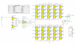
So, I have an idea to build a speaker amp with multiple buf634a. This is a schematic for the amp.

The amp has 3 stages to boost the power
1. input buffer with a dual opamp, opa1642
2. signal amplifying using the mbl6010d preamp circuit (dc blocking without a capacitor...), two opa1611.
3. each channel has 5 buf634a to increase the current (the opa1611 in the schematic is the socket for the buf634a)
Any comment, or recommedation will be welcomed!
Thanks in adavance.
Currently, I'm using a homebuilt opa1642 + buf634a headphone amp. And i'm happy with it.
So, I have an idea to build a speaker amp with multiple buf634a. This is a schematic for the amp.
The amp has 3 stages to boost the power
1. input buffer with a dual opamp, opa1642
2. signal amplifying using the mbl6010d preamp circuit (dc blocking without a capacitor...), two opa1611.
3. each channel has 5 buf634a to increase the current (the opa1611 in the schematic is the socket for the buf634a)
Any comment, or recommedation will be welcomed!
Thanks in adavance.
Last edited:
It looks like the Buf amps have internal resistors and the output impedance of each is ~3.5 Ohms in the audio band. 5 of 'em in parallel brings that down to 0.7, which one would think could drive a 4, or 8 Ohm speaker. Your Vcc values isnt shown, so I'm not able to see how much signal you could be getting into the speaker. Assume +/- 15V?
Looking at the Buf spec, its voltage output can only reach about +/- 12.5V at 250 mA continuous load, or 1250 mA with 5 in parallel. I'll assume that's with +/- 18V supplies, the absolute max, because they dont say in that part of their spec.
That would be ~880mA RMS, given +/- peaks of 1250. P = I**2 R, or about 6.2W at 8 Ohm load. +/- 12.5V peaks is about 8.84V RMS, and that is ~ 9.75W into 8 Ohms. One would think it should do it, however, the current would be larger, so, I suspect their 250 mA max dominates in this part
For currents greater than 250 mA (1250 for 5) it's hard to say what happens, because they dont spec operation at higher loads. Looking at what they provide for schematic -

They dont tell you the value of the emitter resistors. Looking at what they do however, when the voltage drop becomes sufficient to turn on the transistors connected to the bases of the output devices, they begin to cut off their drive as an overload or short circuit protection mechanism that's - I assume - non-linear in operation.
So it'd be difficult to say "What about 10W output with 5 devices paralleled - what happens then?" The output signal drop from +/- Vcc value could get get much larger quickly, as the device starts to protect itself with output voltage clipping as a result.
I'd say operating beyond their +/-250 mA spec is getting into undefined territory, as far as how this device will behave. Hope ~ 6W is good enough!
That would be ~880mA RMS, given +/- peaks of 1250. P = I**2 R, or about 6.2W at 8 Ohm load. +/- 12.5V peaks is about 8.84V RMS, and that is ~ 9.75W into 8 Ohms. One would think it should do it, however, the current would be larger, so, I suspect their 250 mA max dominates in this part
For currents greater than 250 mA (1250 for 5) it's hard to say what happens, because they dont spec operation at higher loads. Looking at what they provide for schematic -
They dont tell you the value of the emitter resistors. Looking at what they do however, when the voltage drop becomes sufficient to turn on the transistors connected to the bases of the output devices, they begin to cut off their drive as an overload or short circuit protection mechanism that's - I assume - non-linear in operation.
So it'd be difficult to say "What about 10W output with 5 devices paralleled - what happens then?" The output signal drop from +/- Vcc value could get get much larger quickly, as the device starts to protect itself with output voltage clipping as a result.
I'd say operating beyond their +/-250 mA spec is getting into undefined territory, as far as how this device will behave. Hope ~ 6W is good enough!
You're welcome; I hope you build it and find out I'm wrong - on the good side - it does better than 6 before clipping!Thanks a lot. 6w seems to be enough...
I've had a similar project on the back burner for a really long time. Still hope to get to it eventually.
The attached schematic is still a WIP and only shows 40 of the planned 80 BUF634. TINA throws a fit if I try to simulate with all 80. Does a little over 27Wrms into 8Ω @ 0.0033% THD. Around 50Wrms @ 10% THD. Wish the OPA1632 could tolerate +/-18V like the other parts.
The attached schematic is still a WIP and only shows 40 of the planned 80 BUF634. TINA throws a fit if I try to simulate with all 80. Does a little over 27Wrms into 8Ω @ 0.0033% THD. Around 50Wrms @ 10% THD. Wish the OPA1632 could tolerate +/-18V like the other parts.
Attachments
- Home
- Amplifiers
- Chip Amps
- A parallel BUF634A power amplifier
