I just checked on my board. Did an FFT and found 177kHz "peak" of -86dBV at 177kHz directly after the 8 Volt regulator. After the LC filter it is gone in overall noise.
When a larger capacitor (I used 2,2uF which was at hand..) was applied directly at the output of the regulator the 177kHz also disapears in the noise band. The effective RMS Value was round 1mV. This is all quite harmless. What values did you measure?
When a larger capacitor (I used 2,2uF which was at hand..) was applied directly at the output of the regulator the 177kHz also disapears in the noise band. The effective RMS Value was round 1mV. This is all quite harmless. What values did you measure?
mmm, need to check (measure) this again. I believe I tried and this messed up the DC bias of the other DAC output.
so, if you ground the not used output, what DC voltage did you get on the used one? did you measure this? Will check myself as well
Erm, no I didn't measure the DC offset at the time. I've gone off at a bit of a tangent since then. With the neg grounded, I'm now using a simple CCS'd 6C45 tube gain stage with a ~5.5R, (5.8R in parallel with the original 133R), I/V resistor from the positive out. (Gain of 46, Ia 18mA, biased @ 0.7V with a diode, 2.3V RMS out @ 0dbfs). But I did measure the bias on the DAC positive outs as being 110.5mV with that configuration, (both channels), with the negs grounded, which is what would be expected with 20mA bias @ digital zero.
I just checked on my board. Did an FFT and found 177kHz "peak" of -86dBV at 177kHz directly after the 8 Volt regulator. After the LC filter it is gone in overall noise.
When a larger capacitor (I used 2,2uF which was at hand..) was applied directly at the output of the regulator the 177kHz also disapears in the noise band. The effective RMS Value was round 1mV. This is all quite harmless. What values did you measure?
Not the same situation indeed. One LF80 was very bugging: oscillations around 195 KHz but 500 mV signal. After inductance the voltage was 7.8 V instead of 8V. As I mentionned earlier, more capacitance solved the problem.
I'm reminded of the, "Why do you want to para-feed and put a capacitor directly in the signal path?", argument.... Whilst conveniently ignoring, that in a traditional series feed tube output stage transformer topology, there is typically a large, undesirable, power supply electrolytic in the signal path.
One LF80 was very bugging: oscillations around 195 KHz but 500 mV signal.
Ouch! I checked mine after reading that. A teeny bit worse than Doede measured before the filter, but nothing for me to worry about.
My latest lash.....
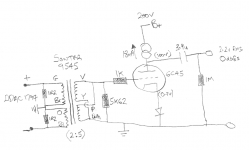
After reading kevinkr's Tube And Transformer I/V Converter For Differential Current DAC thread, I remembered that I have a spare pair of Sowter 9545 I/V transformers.
Sticking with the 6C45 tube output stage that I had been using with a ~5R I/V resistor from the + out, a quick back of an envelope calculation and I soldered 4x 1R2 I/V resistors to the DDAC board. I have the secondaries of the 9545's in parallel, so ratio is 2:5. Output is ~2.2V RMS for 0dbfs signal.
Not had a scope anywhere near it yet, but it sure does sound good!")
After reading kevinkr's Tube And Transformer I/V Converter For Differential Current DAC thread, I remembered that I have a spare pair of Sowter 9545 I/V transformers.
Sticking with the 6C45 tube output stage that I had been using with a ~5R I/V resistor from the + out, a quick back of an envelope calculation and I soldered 4x 1R2 I/V resistors to the DDAC board. I have the secondaries of the 9545's in parallel, so ratio is 2:5. Output is ~2.2V RMS for 0dbfs signal.
Not had a scope anywhere near it yet, but it sure does sound good!
Attachments
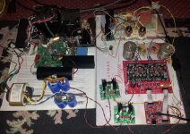
clivem ... is the big black cylinder situated next to the big black box a cap? The function of the black box is ... ? Thanks. Project looks good.
I think you must mean the 100uF/400V Obbligato PSU capacitor. It's a film PS cap. No "nasty" electrolytic caps used here!
The black box.... Not 100% sure what you mean. Directly behind that cap is the HT regulator for the tube output stage. It has a fairly large black heatsink strapped to the cascode transistor. Right at the back/left of the picture, there is a Hammond 370DAX PS transformer (260V-0-260V & 0-6.3V), and next to that is a Hammond 193C choke (20H / 100mA). HT is rectified by the EZ81 tube, and followed with 1uF / 20H / 100uF Pi filter before the regulator.
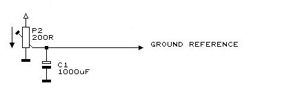
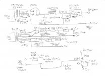
I have attached my power supply schematic, which might make more sense of the picture of a pile of parts and wires. (Apologies for the hand-drawn low quality).
The "black-box" regs used for the 12V and 5V digital sections are these pre-built VERY LOW NOISE <40μV Adjustable Voltage Regulator Board, out 2.5 - 19.5VDC / 3A boards purchased from eBay, based on LT1764. PDF schematic: A-270.
The HT regulator for tube B+ is the Tom Christiansen 21st Century Maida Regulator. (R3=36R. R9=100K. All other components are as per his schematic.)
The reg for the 6C45 tube heater supplies is a Tent Labs Tube Heater Supply, biased up to ~50V from the B+.
Attachments
For the 384kHz, the PCM1794 most likely will be able to do this, but I have not tested this.
Tested!
I've got my on-the-fly sox upsampling set to 8x with the Amanero, for 44.1k source files.
Code:
Amanero Technologies Combo384 Amanero at usb-0000:00:1a.7-1, high speed : USB Au
dio

Playback:
  Status: Running
    Interface = 2
    Altset = 1
    Packet Size = 1024
    Momentary freq = 352750 Hz (0x2c.1800)
    Feedback Format = 8.16
    Packet Size = 0
    Momentary freq = 352800 Hz (0x2c.199a)
  Interface 2
    Altset 1
    Format: S32_LE
    Channels: 2
    Endpoint: 5 OUT (ASYNC)
    Rates: 44100, 48000, 88200, 96000, 176400, 192000, 352800, 384000
    Data packet interval: 125 us
Attachments
I did build two already. One with one deck, and the other with four decks. And now I will make some serious listeningtests. Also with the outputcaps, auricaps vs mundorf silvergoldoil.
It is in mho the best dac I heard. Just sold a totally tweaked v-dac......that little one had space, pinpoint and so on...(and even was better then an Altmann dac) ....but the dddac .... Is another story......it is the beautiful girl standing before you in the most beautiful lingerie........but then for the ears. The secret in audioworld......sssshhhhhht.
It is in mho the best dac I heard. Just sold a totally tweaked v-dac......that little one had space, pinpoint and so on...(and even was better then an Altmann dac) ....but the dddac .... Is another story......it is the beautiful girl standing before you in the most beautiful lingerie........but then for the ears. The secret in audioworld......sssshhhhhht.
Last edited:
Agree with you Jan, the DDDAC is indeed very special. I've heard and owned some very expensive so called highend DAC's but I've never heard any of them do what the DDDAC does.
I built mine first with one board and now with 4 boards. I'm also using Doedes PSU's to power everything.
I built mine first with one board and now with 4 boards. I'm also using Doedes PSU's to power everything.
As Doede also mentioned, I am using his psu, for 12V and 5V. Before I only used a tentlabs psu for the 12V (als o very good) and for the usb Luckit I used the psu of the computer. I have to say there was a big differance between the computers usb psu or the version with the dddac-psu. The last one was obviously the winner. As for the 12V psu, we did some measuring at the owner of Audio-Creative and there the Tentlabs psu did some great work.
For now, I am going to listen to the DDDAC with 1 deck and another with 4 decks, both with the complete DDDAC-psu (12v and 5v).
Music source is a macbook air (late 2011) and I am using Audirvana (after testing the others too).
For real tests I use either Logic 9.2 or Protools 10. Not really for hifi listening, but very accurate. Until now, nothing beats Protools or Logic, but Audirvana Plus came very, very close!
Ordered the 5 v psu as well now. Since I already have an excellent 12v psu.
As CliveM will confirm
, don't forget to change the jumper on the WAVE I/O to enable the external supply.Yes. Thanks. I read that part.As CliveM will confirm , don't forget to change the jumper on the WAVE I/O to enable the external supply.
Glad to be able to learn from the "mistakes" of others.- Home
- Source & Line
- Digital Line Level
- A NOS 192/24 DAC with the PCM1794 (and WaveIO USB input)