Mauro,
I have sucessfully built your "non-inverting GC with inverting power stage" on a breadboard with some P2P. Later I will build a better prototype and post pictures. But first I would like to implement this LM/Buffer so to speak.
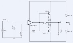
I see there are two schematics. The "Tracking OPamp" and the "Power Current/Current Converter".
My plan is to implement the "Power Current/Current Cunverter" but I did not know if it required the other circuit, or if the two are independant.
If I utilize the PC/CC can I use the LM3886? I have some of them at hand.
Now for input to the PC/CC I was thinking of using a non-inverting opamp circuit with a part like the OAP637 with a BUF634 250ma buffer in the feedback loop so that I have plent of current to drive the PC/CC.
Am I on the right track? Or do I need more than this:
input signal ==> OPA/BUF ==> PC/CC ==> load
Thanks for helping a beginner.
EDIT: I am an idiot, just saw on the schematic you note that Lm3886 is interchangable on this circuit. Sorry for the dumb question.
I have sucessfully built your "non-inverting GC with inverting power stage" on a breadboard with some P2P. Later I will build a better prototype and post pictures. But first I would like to implement this LM/Buffer so to speak.
I see there are two schematics. The "Tracking OPamp" and the "Power Current/Current Converter".
My plan is to implement the "Power Current/Current Cunverter" but I did not know if it required the other circuit, or if the two are independant.
If I utilize the PC/CC can I use the LM3886? I have some of them at hand.
Now for input to the PC/CC I was thinking of using a non-inverting opamp circuit with a part like the OAP637 with a BUF634 250ma buffer in the feedback loop so that I have plent of current to drive the PC/CC.
Am I on the right track? Or do I need more than this:
input signal ==> OPA/BUF ==> PC/CC ==> load
Thanks for helping a beginner.
EDIT: I am an idiot, just saw on the schematic you note that Lm3886 is interchangable on this circuit. Sorry for the dumb question.
Excuse for the delay of the answer.
If she it uses OPA637 is not necessary to use a Output buffer, because the gain of 1000 of PC/CC is suited to the current with exit of the chip. In fact, PC/CC works well with the values of the scheme, but as emerges from the debate with Jan, to get the maximum thing by this circuit be necessary use a tall impedance of exit and gain about to 100 A/A. to do the enough it increase R5 ( es. 0.22ohm ) and reduce R6 ( es. 47 or 22 ohms ). In this case it becomes necessary use a buffer on the Voltage driver, because the INput current ( from PC/CC ) increases. The advantage is that the driver control better the bridge, and the sound becomes more "disposition"
Ciao
Mauro
Forgive me, but the Stasis power stage is a current source, isn't it? If You keep it outside the feedback loop, what about the output resistance. I do not pretend a damping Factor of 1000, but, I'm little skeptical about current driven loudspeaker.
Am I missed something?
How can be obtained the low Rout by the Stasis amplifier?
Am I missed something?
How can be obtained the low Rout by the Stasis amplifier?
So, the concept is to have a good low power amplifier voltage coupled to the load thru a quite high resistor and a current booster that sense the current requested from the load and provide the most part of it.
Output impedance is what there is between low power amp and the load diveded by the current gain of the power booster, so can be keept quite low with
Is similar to this simplified form, used as opamp booster in some industrial application:
Tr 1 and Tr2 are poor current sources but the principle should be correct, is so mandatory to have a high impedance current source?
Attachments
There was a power-amp by Musical Fidelity, model A370, that also used an LM318 on the first stage, boosted by ten MOSFETs at the output.
Apparently it was class-A, but I am not too sure of that. It was released in the mid '80s, if I am not wrong, and it seemed to get good reviews.
Carlos
Apparently it was class-A, but I am not too sure of that. It was released in the mid '80s, if I am not wrong, and it seemed to get good reviews.
Carlos
Attachments
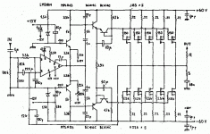
Hi, Carlos
I have quoted the similes with my circuit of A370 here:
http://www.diyaudio.com/forums/showthread.php?threadid=62483
The mosfets are polarized to 1A total, then it's class AB...
This circuits are not "STASIS"...
ciao
Mauro
I have quoted the similes with my circuit of A370 here:
http://www.diyaudio.com/forums/showthread.php?threadid=62483
The mosfets are polarized to 1A total, then it's class AB...
This circuits are not "STASIS"...
ciao
Mauro
Hi Mauro and all other,
I've seen Mauro's work here and find it quite intersting to build the PC/CC. Therefore, I made a PCB layout and etched them yesterday. Now I'm waiting for the parts to stuff the board. I'll inform you about the results then as soon as possible.")
Raphael
I've seen Mauro's work here and find it quite intersting to build the PC/CC. Therefore, I made a PCB layout and etched them yesterday. Now I'm waiting for the parts to stuff the board. I'll inform you about the results then as soon as possible.
Raphael
Very interesting. Hope to hear more on the results!Hi Mauro and all other,
I've seen Mauro's work here and find it quite intersting to build the PC/CC. Therefore, I made a PCB layout and etched them yesterday. Now I'm waiting for the parts to stuff the board. I'll inform you about the results then as soon as possible.
Raphael
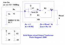
I have tried a different yet similar approach. I have prototyped the circuit shown below using an LM3875. It works just fine (and sounds very good, too!) using a tube "front-end" (actually a 12b4 SE preamp!).
The circuit is perfectly stable as far as the drive impedance (Rs) is high enough compared to R1.
The circuit is perfectly stable as far as the drive impedance (Rs) is high enough compared to R1.
Attachments
Last edited:
- Status
- This old topic is closed. If you want to reopen this topic, contact a moderator using the "Report Post" button.
- Home
- Amplifiers
- Chip Amps
- A LM3886 "Stasis" Power Buffer