
Thanks. Well Tempered makes some odd turntables, but I really like how they perform.
BTW, I inserted the 1626 SET amp in between the preamp (it's also a 1 wpc integrated) and the F4 and it was a very satisfying result. As far as power goes, with my preamp I have to turn it up all the way to get "slightly louder than normal" for my tastes and 97 dB speakers--feels like about 5 wpc. With the SET providing the voltage swings, I'd estimate I'm getting maybe 10-15 watts per channel. Now I'm thinking about trying an Impasse preamp. One more thing I need to try is using the LTA's integrated speaker output into the F4.
BTW, I inserted the 1626 SET amp in between the preamp (it's also a 1 wpc integrated) and the F4 and it was a very satisfying result. As far as power goes, with my preamp I have to turn it up all the way to get "slightly louder than normal" for my tastes and 97 dB speakers--feels like about 5 wpc. With the SET providing the voltage swings, I'd estimate I'm getting maybe 10-15 watts per channel. Now I'm thinking about trying an Impasse preamp. One more thing I need to try is using the LTA's integrated speaker output into the F4.
Thanks, ZM! Now to decide whether to futz with it or just keep moving forward... I have a feeling I won't be able to sleep quite right with that LED not working. Which brings me to a question: I clearly have a hard time deciphering the polarity of the LED placement on the PSU from the markings on the PCB (I'm using the Universal Power Supply boards). And I don't see an LED on the PSU schematic for reference. Any recommendations for getting it right the first time?
Yes, it's a 10Kohm resistor. Same as the other side of the PSU, on which the LED is working fine.
long LED pin going to more positive rail
for each rail V, take 1K and you're done
if LED is still screaming in your eye, just increase it for 30%
so, for usual Papamp rail, in vicinity of 22V5dc, start with 22K, small one
Finished up an F4 a couple days ago. Wow, what an amazing amp! I’m pushing it with a BA3 FE/Pre, so kinda like a BA3 ‘proper.’ Using two 20v /300VA donuts for power. Thanks to everyone who answered my questions, and to NP for the superb design!
Attachments
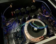
Finished up an F4 a couple days ago. Wow, what an amazing amp! I’m pushing it with a BA3 FE/Pre, so kinda like a BA3 ‘proper.’ Using two 20v /300VA donuts for power. Thanks to everyone who answered my questions, and to NP for the superb design!
Congrats!


Lookin' good Eggsy
I’ve spent too much time thinking about what this could mean
Another F4 lives!
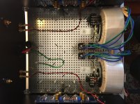
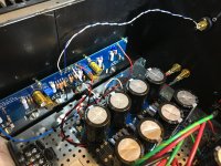
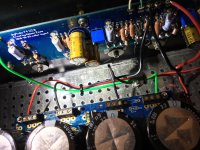
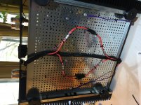
After finishing an Aleph J for myself earlier this year, I set out to build an amp for my friend Alex, who I blame for getting me into all this DIY Audio business in the first place, and who first told me about FirstWatt and NP. I settled on the F4. It went live last week and I've been listening to it all week. This amp is INCREDIBLE. My eyes got a bit misty on the first listen, it sounded that good. The Aleph J is also incredible, and as many others have said, it's kind of like comparing different versions of perfection... But there's something special about the F4.
I built it dual mono, but did a test run initially with a single PSU. The dual mono elevates it a bit, but not by much. It sounds absolutely fantastic with a single PSU. 6L6 wisely encourages first-time builders to just build these things stock and then get fancy from there. I'm stubborn, though, and built my first FW project (the Aleph J) dual mono. Now, having tested the F4 with the single PSU before switching over to dual mono, I see what he means. It's a nice addition, but not at all necessary to have an amazing sounding amp.
I also enjoyed the benefit of being able to apply lessons I learned from the Aleph J build in terms of layout and wire routing. I made things a bit cleaner and am overall more happy with how it turned out. Oh, yeah, and it is DEAD quiet. No speaker thump on power up/down, either.
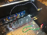
The one matter which continues to stump me are the LEDs. Two questions, if nothing else for ease of mind:
1) One of the LEDs on the left channel PSU dims immediately when I turn off the amp; the other LED stays lit for a while longer. The right channel PSU LEDs dim at the same rate. Why would that one LED dim so much faster than the others?
2) Neither of the F4 board LEDs light up. There are two sets of holes on the PCB - does it matter which set the LED goes in? I put it in the upper set, but then I looked more closely at 6L6's pics in the build guide and see that his LEDs are in the lower set of holes. Any suggestions for desoldering and removing the LEDs from the top of the board? At this point it doesn't seem worth it to go to the trouble of actually removing the boards.
Thanks, as always, to 6L6 for the build guide, and to this incredibly generous community for all the help and encouragement along the way!
Signal chain: Project turntable > Lounge Audio Phono Pre > BA3FE > F4 > Fostex 206E drivers in back loaded horn enclosures.
After finishing an Aleph J for myself earlier this year, I set out to build an amp for my friend Alex, who I blame for getting me into all this DIY Audio business in the first place, and who first told me about FirstWatt and NP. I settled on the F4. It went live last week and I've been listening to it all week. This amp is INCREDIBLE. My eyes got a bit misty on the first listen, it sounded that good. The Aleph J is also incredible, and as many others have said, it's kind of like comparing different versions of perfection... But there's something special about the F4.
I built it dual mono, but did a test run initially with a single PSU. The dual mono elevates it a bit, but not by much. It sounds absolutely fantastic with a single PSU. 6L6 wisely encourages first-time builders to just build these things stock and then get fancy from there. I'm stubborn, though, and built my first FW project (the Aleph J) dual mono. Now, having tested the F4 with the single PSU before switching over to dual mono, I see what he means. It's a nice addition, but not at all necessary to have an amazing sounding amp.
I also enjoyed the benefit of being able to apply lessons I learned from the Aleph J build in terms of layout and wire routing. I made things a bit cleaner and am overall more happy with how it turned out. Oh, yeah, and it is DEAD quiet. No speaker thump on power up/down, either.
The one matter which continues to stump me are the LEDs. Two questions, if nothing else for ease of mind:
1) One of the LEDs on the left channel PSU dims immediately when I turn off the amp; the other LED stays lit for a while longer. The right channel PSU LEDs dim at the same rate. Why would that one LED dim so much faster than the others?
2) Neither of the F4 board LEDs light up. There are two sets of holes on the PCB - does it matter which set the LED goes in? I put it in the upper set, but then I looked more closely at 6L6's pics in the build guide and see that his LEDs are in the lower set of holes. Any suggestions for desoldering and removing the LEDs from the top of the board? At this point it doesn't seem worth it to go to the trouble of actually removing the boards.
Thanks, as always, to 6L6 for the build guide, and to this incredibly generous community for all the help and encouragement along the way!
Signal chain: Project turntable > Lounge Audio Phono Pre > BA3FE > F4 > Fostex 206E drivers in back loaded horn enclosures.
Attachments
@Spryor - Congratulations on yet another fantastic build. I strongly recommend that you get into the hobby of building vintage Ferraris. Even though I don't do it, you can blame me later.  Seriously though, what a gracious gift!
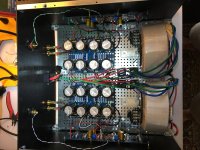
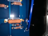
I am not noticing two (upper and lower) LED locations on the boards. I checked that your board revision and mine match. I also did a quick check in the guide. I don't see 6L6s in different locations. I may be light on sleep though. Yours are where mine and his are. Your blue one next to V+. Just check the schematic and ensure that they're turned the right way around, perhaps. Can't tell for certain from the pic. Flat side (as marked by the line) faces away from the V+ wire.
Edited to add - I zoomed WAY in on your photo and looked at the back of my boards. I see what you mean. No. It does not matter which holes. Same traces. Sorry for any confusion.
Seriously though, what a gracious gift! I am not noticing two (upper and lower) LED locations on the boards. I checked that your board revision and mine match. I also did a quick check in the guide. I don't see 6L6s in different locations. I may be light on sleep though. Yours are where mine and his are. Your blue one next to V+. Just check the schematic and ensure that they're turned the right way around, perhaps. Can't tell for certain from the pic. Flat side (as marked by the line) faces away from the V+ wire.
Edited to add - I zoomed WAY in on your photo and looked at the back of my boards. I see what you mean. No. It does not matter which holes. Same traces. Sorry for any confusion.
Last edited:
For those who know the workings of this design well: What is the consequence of using the outdated value of 22.1k vs 27.4k at R8? I referenced the store schematic instead of Nelson’s updated version (attached) when I built my F4. Note that I did go with 5k for R6
Attachments
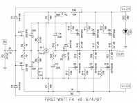
It allows for higher Vgs voltage for biasing. If you managed to bias up the
output devices then you are fine.
Perfect - thanks!
Looks good! I really like your comparison with Aleph J - they really are two different kinds of perfect!!
I don’t think it matters which LED location you used. Did they light up initially, then burn out?
Thanks, @codyt! The LEDs did not light up initially... so I must have put them in backwards. Oh, well. As long as it's working like it should, I think I can let the LED issues go.
@Spryor - Congratulations on yet another fantastic build. I strongly recommend that you get into the hobby of building vintage Ferraris. Even though I don't do it, you can blame me later.
@ItsAllInMyHead - Haha! Your recommendation is duly noted. If I ever get into that hobby, you're officially to blame. ;-) Also, I must thank you for all your posts with documentation and pics of your builds - they have been super helpful as I built mine.
@spryor: A bit of a mystery with those LEDs but congratulations on your build!
Thanks, Dennis, and thanks for your help on the mosfet matching front!
- Home
- Amplifiers
- Pass Labs
- A guide to building the Pass F4 amplifier