Hi Andrew,
It's a nominal 24VDC+/- supply* and~ 13V are asked of it, per board. That should be ok, yes?
I'm going to use the provision for the board's led, change the resistor, and make it a remote (to the front of the amp) string of 4 LEDs.
The data on the LED package says FV 3-3.2 , 24mA. Nothing should be stressed at the planned (by using a 1k resistor yielding 12 mA) current. Or so my novice e-brain concludes ok, yes?
*from a 500VA transformer.
It's a nominal 24VDC+/- supply* and~ 13V are asked of it, per board. That should be ok, yes?
I'm going to use the provision for the board's led, change the resistor, and make it a remote (to the front of the amp) string of 4 LEDs.
The data on the LED package says FV 3-3.2 , 24mA. Nothing should be stressed at the planned (by using a 1k resistor yielding 12 mA) current. Or so my novice e-brain concludes
ok, yes?*from a 500VA transformer.
making music
OK, I did find a 1K/2W and lights are lit!
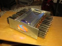
It took some fussy recalibration on the bias; I'm not so sure I'd go this route again with so many LEDs - maybe just two and use thinner opal plex.
The sound is kinda stunning. I am stunned that my recordings sound so different from how I have known them. The F4 is brutal in that it shines a strong light on every aspect of every recording (I'm listening to vinyl mostly), so much so that for the first time I can hear differences in recording quality track to track that I knew might have existed before but now appear stark and clear. My best friend would say, :It'll show you where you live."
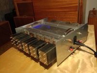
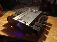
This build was the toughest yet for me mostly because I tried to put everything in so small a chassis. It turned out fine. Silent running...
Everything about the casework is scrap yard chic and from freehand cutting. Aluminium is pretty easy to work even if metal shavings are hard to collect and keep out of the soldering area...
I just love that this amazing amp comes from such humble beginnings brought to life by the kindness of strangers and a singular motovation. Very cool, thank you all so very much!
Nelson, you're a good man.
Cheers!
OK, I did find a 1K/2W and lights are lit!
It took some fussy recalibration on the bias; I'm not so sure I'd go this route again with so many LEDs - maybe just two and use thinner opal plex.
The sound is kinda stunning. I am stunned that my recordings sound so different from how I have known them. The F4 is brutal in that it shines a strong light on every aspect of every recording (I'm listening to vinyl mostly), so much so that for the first time I can hear differences in recording quality track to track that I knew might have existed before but now appear stark and clear. My best friend would say, :It'll show you where you live."
This build was the toughest yet for me mostly because I tried to put everything in so small a chassis. It turned out fine. Silent running...
Everything about the casework is scrap yard chic and from freehand cutting. Aluminium is pretty easy to work even if metal shavings are hard to collect and keep out of the soldering area...
I just love that this amazing amp comes from such humble beginnings brought to life by the kindness of strangers and a singular motovation. Very cool, thank you all so very much!
Nelson, you're a good man.
Cheers!
Attachments
-
 bottom plate.jpg334.2 KB · Views: 507
 -
 rear pannel.jpg280 KB · Views: 285
 -
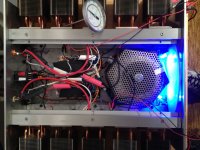 overhead running.jpg369.9 KB · Views: 290
 -
 left channel placed.jpg466 KB · Views: 286
 -
 left channel loose.jpg748.5 KB · Views: 458
 -
 dark and lit.jpg288 KB · Views: 464
 -
 three quarter bright.jpg291.4 KB · Views: 497
 -
 cold on cardboard.jpg347 KB · Views: 507

Whahoo! I got the fugly indeed from ZM! I am honored.
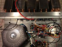
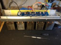
The caps are hot glued on a perforated piece of plex which is then screwed to the bottom plate. There is also a wooden block that holds the resistor complement and adds strength to the assembly.
The amp gets to almost 90 degrees F after 90 minutes of working. The switches I put in as a precaution agains "thump" at turn on of turn off but turned out not to be needed.
you got Fugly! for idea and craftmanship ......... from which I can read amount of love and care
electrically (tidier wiring) and some work around caps (raw pcb- exacto knife-small drill and you have PSU pcb , which represents much more secure solution , comparing to timrawsonlike hot glue approach) ........ and I'll add second !
electrically (tidier wiring) and some work around caps (raw pcb- exacto knife-small drill and you have PSU pcb , which represents much more secure solution , comparing to timrawsonlike hot glue approach) ........ and I'll add second !
You are right ZM. I should learn the process of PCB making and probably will in time.
The diyAudio PSU boards are great but too large for this/my build.
The caps are indeed up off the floor and insulated and quite well secured. The wires do have some order to them, length enough to have some play and lay well with each other. I used some heavy sheet rubber to create layers... It aint pretty but it's not a mess (see attached). Still, I will strive one day to recieve your double fugly
Attachments
mcandmar...
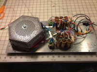
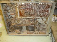
The metal around the torroid was an attemt at containing the magnetic field. IT floats above the torroid and does not touch it. Usually this kind of surrounding is made of heavy metal (iron/steel) and does indeed connect to the mounting bolt but any contigous screen should also help.
I'm working with scrap metal. I do what I can
mcandmar...
The metal around the torroid was an attemt at containing the magnetic field. IT floats above the torroid and does not touch it. Usually this kind of surrounding is made of heavy metal (iron/steel) and does indeed connect to the mounting bolt but any contigous screen should also help.
I'm working with scrap metal. I do what I can
The metal surrounding the toroid is pretty solid tech; it's a Faraday cage.
Just as a point of clarification:
I have been told that one ought to ensure that the bolt holding the toroid down to the chassis ought to be insulated from the top of the chassis. ie. "Don't let the top of the bolt touch the case.".
Is is true then that the bottom of the bolt should also not touch the case? or is it just that we don't want top *and* bottom to be touching the case at the same time?
......is it just that we don't want top *and* bottom to be touching the case at the same time?
like that ;
imagine piece of wire instead of bolt ; if you , in ant way , form that piece that ends meet - there is short turn in magnetic field ....... same as when you connect both ends of secondary together
boom
big badaboom
Attachments

I bolt my toroids through the chassis (or through a securing plate fixed to the chassis).
I insulate the top of the bolt and it's dished washer plate with at least 2 layers of very robust tape, or 4 layers of thinner tape.
That way someone falling on top of an amplifier and crushing the lid down onto the toroid fixing does not create a shorted turn.
Or for very flimsy construction with a tiny gap from lid to bolt/washer, where a tiny 1year old finger pressing would otherwise create a shorted turn.
- Home
- Amplifiers
- Pass Labs
- A guide to building the Pass F4 amplifier