But can it survive long enough for the Fault Current to blow the Mains fuse and for the arc to extinguish?
What fault current?
Have you seen a test of this assembly?
Can it survive a kA event and survive long enough to Blow the mains fuse and allow time for the arc to extinguish?
Just exactly what sort of "kA' event are you suggesting?
"normal" your slaking Andrew, however...A CL60 is designed to pass "normal" currents..
This is totally confusing? What did you test exactly, the CL-60 ? A brigde gnd isolation circuit like Pass sometimes uses? And exactly how did you test it? What blew up or made an explosion? And what was not damaged?I asked a few times about the modified Bridge Rectifier version of the Disconnecting Network.
No Member came forward with evidence of "safe" to use" as suggested.
I tested it.
The size of the explosion surprised me.
Even more surprising was that I could not detect any damage or changed parameters in the Disconnecting Network components.
I now recommend the bridge rectifier Disconnecting Network.
I have never put a CL60 to such a "test".....
Well, I'm not trying to find "evidence" at the moment but, UL certification is good enough for me and if Pass dosent have it, I know other equipment such as the GFA stuff that does and it uses the same GND isolation schemeMaybe you should try to find "evidence" that what you and Pass are suggesting is safe on 110/120Vac fault currents.
")
I have sufficient experience with voltage from lightning to uV and currents from my welder to pacemaker inputs. I'm just trying to understand your concern. I don't
read my report from quite a few years ago. All the details that I needed were in there.
Short the Live to the Chassis and Fault Current flows.
The higher that fault current the quicker the fuse ruptures.
The lower the fault current the longer the fuse takes to rupture.
Make the circuit impedance too high and the fuse may never rupture.
What happens to a CL60 during a fault current incident?
I did not know what happens to a diode bridge during a fault current incident, so I asked.
In the end I did a fault current test.
Go and read about it.
I don't understand "slaking""normal" your slaking Andrew, however......................
I don't understand "slaking"
A slang term for not trying hard enough. Maybe I don't know the spelling, it's slang.
It was meant as a touch of humor
The live wire must be after the fuse but, circuit imp to high? A shorted live wire to chasis?...Short the Live to the Chassis and Fault Current flows.
The higher that fault current the quicker the fuse ruptures.
The lower the fault current the longer the fuse takes to rupture.
Make the circuit impedance too high and the fuse may never rupture...
But, I thought we were talking about the PSU GND, after the xfmr? One of those live wires does not have the capability to pass "kA"s due to all the other losses in the system and your house wiring, breakers etc. If engineered correctly, the mass of copper etc. wont be melting or whatever before the few amp fuse goes
You mean when a 25V wire falls off and goes to psu GND. It starts to get warm and goes from 10 ohms to 2 ohms or some such. But, the input fuse might go? 25V dosent bother me....What happens to a CL60 during a fault current incident?....
Could you help me a tad more with finding your report. I'll search but give me a good keyword if you would....In the end I did a fault current test.
Go and read about it.
Disconnecting Network, test with Fault Current
it starts here
http://www.diyaudio.com/forums/chip-amps/92673-yet-another-3886-gain-clone-3.html#post1357794
and reported here
http://www.diyaudio.com/forums/chip-amps/92673-yet-another-3886-gain-clone-3.html#post1357794
it starts here
http://www.diyaudio.com/forums/chip-amps/92673-yet-another-3886-gain-clone-3.html#post1357794
and reported here
http://www.diyaudio.com/forums/chip-amps/92673-yet-another-3886-gain-clone-3.html#post1357794
O.K. Basically, a live mains wire falls off onto PSU GND.
First, I gotta say, always pass through the IEC plug/switch/filter/fuse holder components with no extra wires before the fuse or anywhere else. Connect the earth GND as soon as possible to the case without excess wire!
This will likely prevent the above senerio from ever happening
However, maybe you want to run your switch to the front Panel. Just do it after the fuse!
So, somehow we get 110Vrms on our pcb, or lets say PSU GND. That live wire is looking for Nuetral or Earth GND, hopefully it dosent find you first! Going through the same type CL-60 thermister that is on the transformer, to Earth GND, sure dosent sound dangerous to me. It is there continuosly on the xfmr input Trouble here is, you have 240Vrms right? Some adjustment could be necessary with the thermistor but I don't think that is a difficult issue. So the 110Vrms lands on a 10 ohm Thermistor. Momentarily, 16.5A + or - flows through it, rising rapidly as the resistance goes down, and the fuse blows...
Some other thoughts:
If this was the issue, why did you connect across Live to nuetral and not live to earth during your test? In the US our Nuetral is connected at the breaker/fuse box to Earth.
Pass uses 400V 35A bridges like you I think I read and those things are quite robust in nature. Possibly necessary for some safety issues. People using schottky diodes might want to reconsider.
But, I'm thinking the real fault you tested was your torocaca fuse holder and or fuse? Even if you had a 10Ga. wire shorting the Line to nuetral that fuse should not have done that!
First, I gotta say, always pass through the IEC plug/switch/filter/fuse holder components with no extra wires before the fuse or anywhere else. Connect the earth GND as soon as possible to the case without excess wire!
This will likely prevent the above senerio from ever happening
However, maybe you want to run your switch to the front Panel. Just do it after the fuse!
So, somehow we get 110Vrms on our pcb, or lets say PSU GND. That live wire is looking for Nuetral or Earth GND, hopefully it dosent find you first! Going through the same type CL-60 thermister that is on the transformer, to Earth GND, sure dosent sound dangerous to me. It is there continuosly on the xfmr input
Trouble here is, you have 240Vrms right? Some adjustment could be necessary with the thermistor but I don't think that is a difficult issue. So the 110Vrms lands on a 10 ohm Thermistor. Momentarily, 16.5A + or - flows through it, rising rapidly as the resistance goes down, and the fuse blows...Some other thoughts:
If this was the issue, why did you connect across Live to nuetral and not live to earth during your test? In the US our Nuetral is connected at the breaker/fuse box to Earth.
Pass uses 400V 35A bridges like you I think I read and those things are quite robust in nature. Possibly necessary for some safety issues. People using schottky diodes might want to reconsider.
But, I'm thinking the real fault you tested was your torocaca fuse holder and or fuse? Even if you had a 10Ga. wire shorting the Line to nuetral that fuse should not have done that!
That would be the same Residual-current device - Wikipedia, the free encyclopedia
We, atleast in Sweden have them for almost everything in homes.
We, atleast in Sweden have them for almost everything in homes.
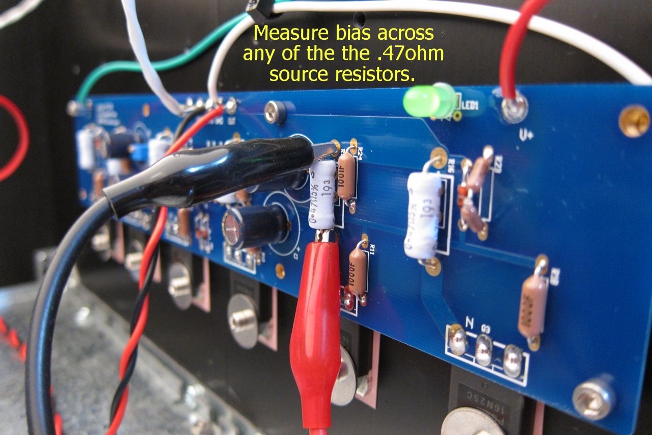
The voltage is high because there is no load. It will get lower in normal operation.
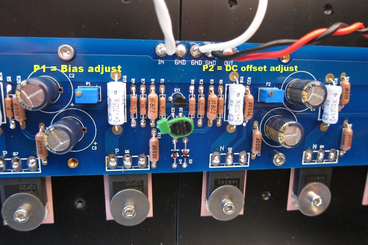
I'm 95% confident that the bias pot should react the the "normal" way, clockwise should turn things up, counter-clockwise down. (It's been awhile since this amp was in the chassis...)
I'm 95% confident that the bias pot should react the the "normal" way, clockwise should turn things up, counter-clockwise down. (It's been awhile since this amp was in the chassis...)
Last edited:
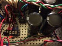
In keeping with the past few safety minded posts, the charged caps can be very dangerous. For instance, not waiting for the caps to discharge and using a screwdriver across their terminals, will screw up the screwdriver, make a bang like you probably havent heard in your house before, blind you, and cause you to jump back and hit something. Maybe other unwanted things also.
- Home
- Amplifiers
- Pass Labs
- A guide to building the Pass F4 amplifier