This afternoon I thought I'd give some time to think about the problems involved in laying a flat wire in a slot shape. A year or so ago I did think about this and even spoke to Russ Gries who did a 3D printer conversion which was awesome, he was laying wire in weird shape, though there was a prevision that the shape didn't get to narrow.
However I'm sure Russ has overcome this issue. If you have no idea what I'm on about, then have a look at his work - 50 AWG Spiral Coils? Sprial Coil Overview. V2.0 CNC Flat Coil Winder. RWG-OSD - YouTube
This morning I thought that the best way of laying wire in a slot shape would require tension, so I started to play on Fusion and see what I can come up with.
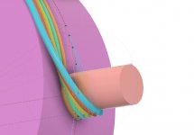
The issue with using cylinders are, the wires will always clump together at the ends. So I started to think what would happen if you changed the angle of the end cylinders?
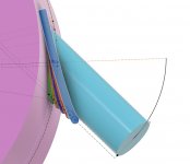
If you compare the two angles of the tangent cylinders, you increase the radius of the Nth wire.
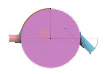
What you're trying to replicate is the flat slot shape, which is basically a ratio of Pi.
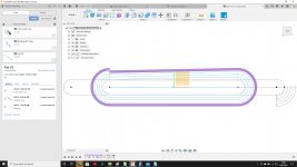
What I ended up creating was a spreadsheet which allowed me to change the gauge of the wire, the radius of the outer cylinders the radius of the master cylinder which determines the overall slot length, the angles of the outer cylinders required, ohms etc etc... however I now have to reverse the equations to speed things up.
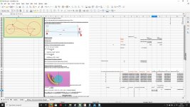
For the moment, the cylinder technique works in respect of that is make a perfect tension, though I'm only tried hand winding.
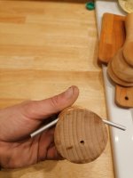
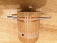
This is how tight the wire was when using AWG40
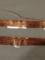
Though I doubt I'll ever have to time to convert this to a mechanical winding machine, it has dawned on me that this maybe a lot easy than Russ' excellent creation.
However I'm sure Russ has overcome this issue. If you have no idea what I'm on about, then have a look at his work - 50 AWG Spiral Coils? Sprial Coil Overview. V2.0 CNC Flat Coil Winder. RWG-OSD - YouTube
This morning I thought that the best way of laying wire in a slot shape would require tension, so I started to play on Fusion and see what I can come up with.
An externally hosted image should be here but it was not working when we last tested it.

The issue with using cylinders are, the wires will always clump together at the ends. So I started to think what would happen if you changed the angle of the end cylinders?
An externally hosted image should be here but it was not working when we last tested it.

If you compare the two angles of the tangent cylinders, you increase the radius of the Nth wire.
An externally hosted image should be here but it was not working when we last tested it.

What you're trying to replicate is the flat slot shape, which is basically a ratio of Pi.
An externally hosted image should be here but it was not working when we last tested it.

What I ended up creating was a spreadsheet which allowed me to change the gauge of the wire, the radius of the outer cylinders the radius of the master cylinder which determines the overall slot length, the angles of the outer cylinders required, ohms etc etc... however I now have to reverse the equations to speed things up.
An externally hosted image should be here but it was not working when we last tested it.

For the moment, the cylinder technique works in respect of that is make a perfect tension, though I'm only tried hand winding.
An externally hosted image should be here but it was not working when we last tested it.

An externally hosted image should be here but it was not working when we last tested it.

This is how tight the wire was when using AWG40
An externally hosted image should be here but it was not working when we last tested it.

Though I doubt I'll ever have to time to convert this to a mechanical winding machine, it has dawned on me that this maybe a lot easy than Russ' excellent creation.
Last edited:
not sure if you ever watched the video  but in my intro there is such a thing. to lay flat coils
  and yeah. there is only so much you can do when making a turn, it cant be to small radius
  while round ones could be done nicely.
CNC Pancake Coil winding (Bifilar coil) - YouTube
after that i made a simple jig , and i cant seeem to find the picture it worked great flat and all. ill look for it.
not as nice as the cnc version i had many ideas for such a thing if i could make tighter turns
  more coil more output !
CNC Pancake Coil winding (Bifilar coil) - YouTube
after that i made a simple jig , and i cant seeem to find the picture
not as nice as the cnc version
Last edited:
after that i made a simple jig , and i cant seeem to find the pictureit worked great flat and all. ill look for it.
not as nice as the cnc versioni had many ideas for such a thing if i could make tighter turns
more coil more output !
yes, I remember seeing that video a while back, it works on the basics of a drag knife.
I've finally finished the excel formulas and realised that my cylinder idea actually would yield a tangent length equal to the Nth radius. So at some point the 3D printer will be re-jigged. The idea of winding AWG 50 with a tight turn would be interesting...
Hope your well? You may or may not have noticed, I have given up on FB, I can't stand the platform and to shite it pumps out!
could this information be useful to someone?
8.1.2 Consequences for the development of sound transducers The choice of the material of the plate and, in general, its shape (we are only dealing with the plane radiators here) allows the coincidence frequency to be determined within wide limits. Depending on the dimensions of the plate, one of the above-mentioned work areas can be used specifically for sound radiation or avoided (see [German Physiks 1994]). If we assume finite plates or shells again, the following basic considerations can be made: • High coincidence frequency (fk # fo) In this case, the phase velocity of the flexural wave must be very low. This is the case with materials with a low E · h / ρ ratio, i.e. with very flexible and heavy materials. The bending wave near field at the excitation point generates an almost non-directional sound radiation, as do the edge effects. The efficiency is low, however. • Coincidence frequency in the transmission range (fu <fk <fo) The converter works below fk as a piston with "acoustically short-circuited" bending wave radiation, above fk as a bending wave oscillator with increasing phase velocity cB. The increasing efficiency above fk and the occurring modes are disadvantageous. • Low coincidence frequency (fk <fu) The sound transducer works with increasing frequency and simultaneously increasing, high phase velocity cB more and more as an ideal piston. As long as the bending wavelength λB is significantly greater than the effective length of the plate or shell, no standing wave can build up due to reflection and the frequency and phase response is balanced. Only when the overall length of the plate or shell reaches the order of magnitude of the wavelength at higher frequencies do standing waves (modes) form. These modes and the frequency-dependent radiation angle are problematic. The dimensioning here has to be exactly different than in the first case: high rigidity (high modulus of elasticity, high related bending stiffness due to the curvature of the shell) and low specific weight. According to [German Physiks 1994], an optimization (reduction of the resonance influences and thus smoothing of the frequency response) can be achieved by influencing the reflections in a targeted manner:
Analytische Berechnung der Schallabstrahlung des ebenen ...
SPSC @ TU Graz › DA_Hiebel_Biegewellenwandler
Winding wire flat
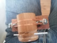
Another foot note continuing from last weeks work on making a flat actuator from AWG40 wire, here is my latest iteration.
So far this has been yielding the best/cleanest winding yet. If you zoom in on the photo, it's still not 100% perfect, but it better that what I've seen on the net, considering it AWG40 which is 0.08mm diameter in new money!
Also, looking back at some old work, I came across an article regarding Quasi Hallbach ironless motors - The voice coil actuator types which are considered: One magnetization... | Download Scientific Diagram
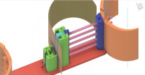
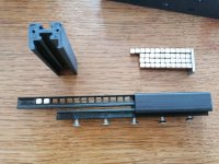
For those who are interested in making one, I designed one which was made and I would be willing to share, (don't expect HiFi quality!) If you have a 3d printer and want to experiment, PM me for this design -
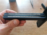
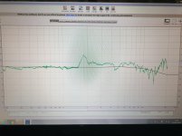
Another foot note continuing from last weeks work on making a flat actuator from AWG40 wire, here is my latest iteration.
So far this has been yielding the best/cleanest winding yet. If you zoom in on the photo, it's still not 100% perfect, but it better that what I've seen on the net, considering it AWG40 which is 0.08mm diameter in new money!

Also, looking back at some old work, I came across an article regarding Quasi Hallbach ironless motors - The voice coil actuator types which are considered: One magnetization... | Download Scientific Diagram
For those who are interested in making one, I designed one which was made and I would be willing to share, (don't expect HiFi quality!) If you have a 3d printer and want to experiment, PM me for this design -


Note about Page 36 - FEMM design.
Going though this thread and there's a lot here, I thought I would make a note about FEMM, which is mentioned around Page 36.
Two points, the first which maybe obvious to some, magnets don't increase in power! All that a well designed motor does is routes the magnetic flux reducing any losses.
Hear is a video showing this -
View attachment FEMM.mp4
Second point, please never be fooled into thinking that you need fancy tools to machine mild still, if you have a table saw, and 10" angle grinding blade, you would be amazed as to what you can achieve.
nice James ! still going strong i see !
Not really, I changed jobs a few months ago, thinking I'd have some extra spare time, turns out im working more than ever, so all audio stuff has gone out the window.
Soft Paper
Hello again
I just have to write it because I'm excited again. I have already read through the whole threat, but have not found any clear statements about the stability of the membrane material and its tonal context. Maybe I overlook something?
Once again I built a new membrane. After the theoretical considerations of my posted text, Hiebel's thesis. The paper I use is always 120gsm. Together with the lacquer, about 180g /qm. So far it was a stable printer paper. So I always had a relatively strong increase in the high frequency range. Which can be annoying at times.
Now I use a soft drawing paper with the usual varnish. Actually against my intuitive considerations. The strong increase in the high frequency range is gone and to my surprise the dynamics and the contouring have increased significantly! The fine drawing is phenomenal!
So use the softest paper possible.
regards
Hello to all and to my friend Wrine (i love your youtube work, keep it up).
I'm not back yet into the rubas because they are working very fine with no problems. The anti humidity treatment that i adeed and laquer is doing a very fine job from preventing the membrane deforming over day or bending and the hand cutter Al coil did not snap or makining noises wich tells me that the small drops of super glue plus laquer is a very reliable sollution (almost 5years now).
As everyone had seened from my tests, the painting/drawing paper is the way to attain a ballanced, well behaved, rich and delightfull sound. I had a couple of thin foils and hybrids (foil+paper) but the sound wasnt on my taste.... (either too bright, or ordinary, or flat sound).
Peril please try rice, cotton or silk paper and report if you can. I used Canson C A grain painting paper.
The only thing i have in mind now is adding a protection fence of stainless steel against the kinds as i have two now, and i was thinking about adding concave shaped horizontall sound difusers as James did (to improve verticall dispersion and distorsion) if i remember right.
Cheers
Sergiu
Diffusor
Hello Sergiu Thank you very much for your work, it helped me to move forward very quickly.
At the moment i'm sticking to the new membrane because it sounds very good. It's very cold in my workshop, around 2 degrees Celsius. In spring I will try to build a ruba with only a semicircle, but with a larger radius. The comb filter effects should then get better.
You write about diffusers with a perforated sheet. I also tested this two weeks ago, but was not satisfied with the minor effect. At the moment I am using an acoustic lens, a scattering lens, which is built about 4cm above and 4cm below the height of the ears. So not at the whole height of the 28cm rubas. It'll be better with that. At the back there is also a diverging lens on the whole height.
regards
Your welkome Peril. Acoustic lens i wanted to say but lost it in my brain...
As a colleague of ours tested silk a few pages back and it lowered the distorsions, i wanted to know if someone have tried cottone or rice to see if i should upgrade.
Thanks and keep up the good work.
As a colleague of ours tested silk a few pages back and it lowered the distorsions, i wanted to know if someone have tried cottone or rice to see if i should upgrade.
Thanks and keep up the good work.
Hi
I am trying to express myself a little more precisely what I will pay attention to in the future when developing a membrane. As I understand it from Hiebel's thesis. You can limit yourself to pages 108-112. So a summary of three different types of bending wave transducers. Who has the opportunity to read with a translation tool. Difficult to understand and actually against intuition.
If I choose a 120 gram paper, I use paper that is as soft as possible so that there is no excessive increase to high frequencies. Together with the lacquer total weight, 180 grams, I will also choose a particularly soft laquer. If it then sounds too aggressive, an additional layer can be applied laquer. The hardness then no longer increases, but the weight does.
That means you always have to consider the stiffness of the paper with the weight of the paper! If you choose particularly light paper together with laquer, you should expect that the paper will no longer achieve the necessary softness. The lighter the membrane, the softer it has to be. (soft plastic can to be better)
The dimension of the membrane and the cushioning also play a role. You have to experiment. I think that a larger radius makes the membrane as a whole more elastic. The triangles of sergiu make the membrane even more elastic and give further benefits at high frequencies.
regards
Hi, the membrane has to be soft and as FIBROUSE as you can get. The laq has to be very stiff not soft, and the membrane will absorb the peaks if it is softer enough. The laq is mandatory to be applied in a very thin layer and only from the coil to outside the cilinder, and 2cm after the top of the cilinder. Because the high freq's are usually a surface vibration. You can apply the very thin coat of laq with a special flat thin hair horse painting brush that you will find on a painting shop on the net. On the rest of the surface of the cillinders you can mix a combo of bees wax as i did and heat apply it to the membrane. It will enhance rigidity to the extreme without adding too much mass. I had absorbed the excess wax with newspaper and a heated iron on the inside of the cillinders. The paper hinges that i tested where a bad ideea because, to be more explicit, it gave a sound as if you have touched a tweeter's membrane with your finger....
Dont waste time with things that had been done before. If it was a good solution i would have adopted it to my finall design allready. If you want to go down to 180hz dont use paper hinges, BUT if you want to go to all that trouble only for a tweeter than go for it. Your choice.
I think the acoustic lens ideea of peril is a very good ideea to experiment with.....
Cheers
Sergiu
Interesting, why should the membrane be fibrous?
Unfortunately I haven't found a “soft laquer” yet, but if I had it I would make the membrane a little lighter. Mass and elasticity are the important parameters. The membrane does not absorb any sharp points! If there is a good relationship between the mass and the elasticity, the efficiency increases less at high frequencies than with a rather stiff membrane. The speed of sound in the air should correspond to the speed of the transverse waves of the membrane. Roughly, but there are other concepts as well. You use wax, I use monacor mdm 20. This material is designed to absorb transversal waves, i.e. structure-borne noise or, as you call it, surface waves. Unfortunately, it adds significant bulk. Nevertheless it is convincing in terms of sound. Have you already tested that? You write something arrogant: if it were a good solution, you would have already adopted it in your design.
My centering spider is made of sylomer. A few lengthways, lifting a little around the membrane at the bottom and pulling down a little around the membrane at the top. A very good solution. Resonance frequency 50 Hz. My rubanoid has “surface waves * from approx. 200 Hz.
My latest development and being tested is a bead (sicke) for the Ruba. Already sounds promising.
I used the acoustic lens with lamellas for a long time. But even this does not completely solve the comb filter problem.
Ps: only use two half cylinders
regards
Fibrouse because it lowers the distors in the mids, and increases stiffness, but where to find a high gr/sqm?
A colleague of ours tested a few pages back in this thread.. And he noted that the rubas sing more clearly...
I found sheets of coottone and other exotics but at 30gr/sqm and small sheets of A4 format for origamy is a no go for me.
I have had a couple of large band 12 inch Alnico speakers wich i loved how they sound compared to others, and they had a very fibrouse and stiff wizzer.
I may have been a litle arrogant (but i didnt want that) as i didnt quite know how to express myself as english isnt my native language.. BUT what i was trying to say is to help you and others to not waste time with things that where tested and drove to a somehow dead end. This kind of stuff also cuts abit the enthusiasm, (to me it did). If you are finding something new that we missed then i'm very curious to read your research, because, as you have seen, my project was made for long term usage and not only for prototypes and research into this concept. Im looking forward for improvements.
I have tested different types of industriall laq to painting laq and applied it from thin to thick, to small/big/whole area and inpregnated or surface apply only to the surface.
The best to me was laq for winding transformers from a motor winding shop, applied in two thin layers from the center of the coil to 1-2cm further from the axis of the cills for horizontall dispersion, and let the core of the membrane do its job at absorbing peaks and resonances.
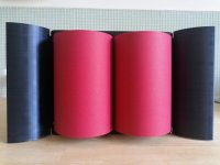
Then i use a mix of bees+paraffin wax to stiffen the latteral further as you can see in the pic bellow.
Please show me that sylomer that you use as elastics. I am very curious how they look, as standard elastics tend to brittle and snap.
Further analising my older writes from my notes i think you are right with your theory that you point out here about vibrations/sound propagation, as i have tested and found out in the past, that the hights are surface propagating waves and the mids propagate almost entirelly in the core, because when you touch the membrane the hights are suffering, the mid-hights suffer less and the mids lesser. But what i want to point out is that the hights peaks and distorsions may be tamed by the stiffnes/softness ratio of the support (our case cilinders) wich the laq is applied to. Thats why i think fibrouse is better, not only for the hights but also for the mids as it tames resonances thus lowers the overall distorsion a abit.
The pics are telling the whole thing as the materials aged nicelly in my case.
I did try half cils but with paper i found out that it is a pain to make the structure stable..
I did try a bunch of soft laqs but didnt like the horisontall dispersion too much . You may find one of them more usefull wich is the varnish sprays used to treat painting from degradation. Its soft and abit elastic also.
Cheers
Attachments
Did you use monacor mdm 20 strips or some kind of surface treatment? If they are strips, i have used something similar. I even atached stripes of wool cords in different patterns. It was also bulky enough to not go further although this sollution was very good for thin plastic/composite foils..
I think, but not tested that, folds done horizontally as in the linaeum patents may be a very very good solution for a part of the problem.
Cheers
I think, but not tested that, folds done horizontally as in the linaeum patents may be a very very good solution for a part of the problem.
Cheers
 [/ATTACH]
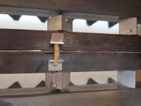
Thanks for your answer. The Sylomer yellow is one of many possibilities. Diameter approx 5mm. front and back, 6 pieces each. In addition, 2 pieces to pull the membrane up and down. Sylomer is a high tech product and will not show any signs of aging
What could be new for you, at least I don't think anyone did this in the forum, a suspension, beading, surround. the photos are twisted? I've been listening to it for a day. at first you hardly hear a change because it is not so obvious. But it sounds very precise and, above all, it benefits the lower frequencies. Impulses are shorter, possibly a little weaker. Do I have to listen a little longer and change the surround a bit. it may be that the membrane has to be corrected with the laquer.
regards
Last edited:
Dear Peril and sergiu2009, have either of you done a simulation in cad to see the standing waves on the diaphragm? It would be interesting to see/do a comparison between live data and a sim.
Taking it one step further, if you PM the dimensions of your diaphragms, plus the arch dimensions, I can sim them for you?
Taking it one step further, if you PM the dimensions of your diaphragms, plus the arch dimensions, I can sim them for you?
- Home
- Loudspeakers
- Planars & Exotics
- A DIY Ribbon Speaker of a different Kind

