Would it be possible to modify the FX 4 to run off IRFP240/9240 mosfets ?
You would get an FH5, based on Apex naming convention (not an actual amp, yet). That’s where the FH9 came from: FX8. I modified the FX8 to use hex FETs. The switch to hex FETs requires addition of a VBE multiplier to compensate for thermal runaway. This adds one more active. The nice thing about FX4 is that it is a singleton input stage - gives dominant second order harmonic distortion.
It could be done but would require a simulation.
Last edited:
Thanks for the reply. I do prefer the sound of a singleton input stage and I have a large 0-80v 800VA transformer lying in my office which would give a dc value of 113v and a couple of IRFP9240 and 240 fets given the price of latfets has gone through the roof. I was thinking of building the EZ MOS by LV but this also a simulated amp or maybe use his Vbe multiplier in the FX4
Attachments
2.2UF 100 VOLTS
i know the value , just wondering what is the purpose of this capacitor ....
What is doing ? I think is some kind of RC filter ?
May be for high freq ?
Thanks for posting this and thank you Apex for all the schematics.
I have a suggestion. Perhaps in the first post containing a lot of schematics, notes could be made to mention is the circuit uses discontinued parts. I found some other amps contain parts which I can not obtain eg Juma's pre-amp.
I have only built a pair Pass ACA so far. It also uses hard to get parts (2SK170/LSK170 , available but expensive).
Thanks,
Graham.
Can anyone please tell me what PRO prefix stands for on some of the Apex designs.
Eg on the A40 and ca10 amps it is between the POS and OUT pads.
Thank You,
Graham.
link to ca10 schematic:-
https://www.diyaudio.com/forums/att...00w-ultimate-fidelity-amplifier-apex-ca10-jpg
Eg on the A40 and ca10 amps it is between the POS and OUT pads.
Thank You,
Graham.
link to ca10 schematic:-
https://www.diyaudio.com/forums/att...00w-ultimate-fidelity-amplifier-apex-ca10-jpg
Last edited:
Thanks for posting this and thank you Apex for all the schematics.
I have a suggestion. Perhaps in the first post containing a lot of schematics, notes could be made to mention is the circuit uses discontinued parts. I found some other amps contain parts which I can not obtain eg Juma's pre-amp.
I have only built a pair Pass ACA so far. It also uses hard to get parts (2SK170/LSK170 , available but expensive).
Thanks,
Graham.
Most of the actives in Apex amps are not unique. That is, an equivalent substitute can usually be found. The only exception are the lateral MOSFETs. Which is why I made the FH9, based on FX8 but without the laterals. Most BJTs can be found or substituted.
The Alpha BB uses the Aksa Lender front end which is not your usual balanced input that nullifies even order distortion and contains higher order odd distortion. If you look carefully you will see that the VAS is a single KSC1845 strapped across the two tails of the balanced Long Neck Pair (LNP), not LTP. The Aksa Lender has the advantage of low THD for transparency and dominant 2nd order HD with less 3rd order HD and not much else. Very similar to a SE Class A triode but without the high THD.
The basis of the Aksa Lender is in this Preamp:
AKSA's Lender Preamp with 40Vpp Output
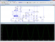
Here is FFT of the Alpha 20 (smaller version) but same profile.
Here is FFT if the Alpha BB, 2.86vrms into 8ohms:
And all of this is done with minimal negative global feedback for flat phase for superb soundstage.
Thanks for sharing details of your drivers. I have not see that tweeter before. Is it like an AMT?
can you imagine what an amp like that (I like it) ... would do with an anal layout ?
PS - your KSC1845/SA992 days are almost over. I've done design changes to drop Vce requirements
to under +/- 60V because of this.
OS
Last edited:
Hi OS,
JPS64 has indeed made a masterpiece layout and not sure if you would classify it as “anal” but it is neat, orderly, symmetric to the extent possible, and very tight with classic signature perforated via stitching throughout. It’s the Alpha Nirvana amp, also discussed in this Forum on another thread.
JPS64 has indeed made a masterpiece layout and not sure if you would classify it as “anal” but it is neat, orderly, symmetric to the extent possible, and very tight with classic signature perforated via stitching throughout. It’s the Alpha Nirvana amp, also discussed in this Forum on another thread.
Hello,Can anyone please tell me what PRO prefix stands for on some of the Apex designs.
Eg on the A40 and ca10 amps it is between the POS and OUT pads.
Thank You,
Graham.
link to ca10 schematic:-
https://www.diyaudio.com/forums/att...00w-ultimate-fidelity-amplifier-apex-ca10-jpg
Can anyone please let me know how the protection works ?
I assume is connects to a separate circuit which would cut power to speakers or amp.
If there is an Apex circuit for this can you please let me know the name of it and I will look for it.
Thanks again,
Graham.
Ps I am planning to make some Apex A40's
You’ll have to search the Apex thread for his speaker protect. It’s relay based if I recall.
A basic one from AliExpress would work too if you are ok with mechanical relays.
For example:
https://a.aliexpress.com/_mKD6SA0
A basic one from AliExpress would work too if you are ok with mechanical relays.
For example:
https://a.aliexpress.com/_mKD6SA0
Thank you,You’ll have to search the Apex thread for his speaker protect. It’s relay based if I recall.
A basic one from AliExpress would work too if you are ok with mechanical relays.
For example:
https://a.aliexpress.com/_mKD6SA0
I will have a look.
hello everyone
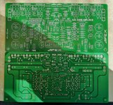
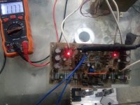
i had my eyes on an apex amplifier for a while now, after seeing a number of successful attempts on this site, i decided to have my go at it, so i printed the motherboard (PCB) at home - bear in mind this isn't my first project - and it turned out pretty good in my opinion, afterwards i wanted to test it, so i used one power transistor 2sa1943 to minimize my loses just in case. and started testing, i found 25v in the emitter and 12v in the output, which is really unusual, its usually less than 5v in the emitter and less than 1v in the output, i kept looking for the error but to no avail, but i have my suspension on two things:
-the 5 KOhm offset adjust variable resistor set on 4.7 KOhm.
-the 500 Ohm bias adjust variable resistor set on 100 Ohm.
and I'm still not sure.
i really need help completing this project. so for anyone offering it here's my questions for you :
-i usually find the SGND and PGND in the same spot unlike the apex's datasheet displays, what would happen if i put them together?
-other then those things what am i missing here?
Attachments
- Home
- Amplifiers
- Solid State
- A Directory of Apex Audio Amplifiers