In fact is the stored energy
in A5 60 Joules (35² x 0,1F)/2
in A3 55 Joules (25² x 0,176F)/2
in A30 37,5 Joules (25² x 0,12F)/2
Maybe the capacity of A30 is enough cause this amp is not as potent as A3 concerning current capacity.
The A5 and A30 are maybe designed rather for 8 Ohms load than for 4 Ohms.
Uli

in A5 60 Joules (35² x 0,1F)/2
in A3 55 Joules (25² x 0,176F)/2
in A30 37,5 Joules (25² x 0,12F)/2
Maybe the capacity of A30 is enough cause this amp is not as potent as A3 concerning current capacity.
The A5 and A30 are maybe designed rather for 8 Ohms load than for 4 Ohms.
Uli
I think there are some interesting project infront of me 
first this A3/A5 crosser and after that, when I'll save enough $$ to complete the "ultimate Aleph project" I have in mind an Integrated Aleph combining A5+ and AP 1.7
In somewhere in between time to finnaly finalize MiniA/BoZ combination ...
first this A3/A5 crosser and after that, when I'll save enough $$ to complete the "ultimate Aleph project" I have in mind an Integrated Aleph combining A5+ and AP 1.7
In somewhere in between time to finnaly finalize MiniA/BoZ combination ...
Hi Uli,
is the stored energy of a power supply really important? To use it you must reduce the voltage to zero wich is a bit difficult when listening to music.
I think it is more important how much energy you can take out of the power supply for a given voltage drop wich would mean that capacitor size is the important faktor and not the voltage.
William
Chassis models
Hi!
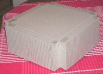
Today I obviously had too much time left so I've build few chassis 3D models ...
The thing is - I have 4pcs of Fischer's SK 56 heatsink - each 145mm high ...
So my first "idea" (more like my interpretation of original mr. Nelson idea) quite some time ago was this:
Hi!
Today I obviously had too much time left so I've build few chassis 3D models ...
The thing is - I have 4pcs of Fischer's SK 56 heatsink - each 145mm high ...
So my first "idea" (more like my interpretation of original mr. Nelson idea) quite some time ago was this:
Attachments
But unfortunatelly I can not squeeze everything inside such chassis - I mean my toridal transfomer is pretty big, and 4pcs of 68000uF/50V Sprague capacitors also needs space - so to somehow squeeze everything in - there would have to be a lot of pretty long wires passing very close to transformer, etc etc .. And I don't like that to much ... - I have some bad experiences with Zen and internal wiring layout ...
So I've thought it out to have some kind of two floor amp - with PSU in gorund floor and circuit in upper (Btw - mr. Nelson - I still think original Aleph's are one of best looking amps ever)
So I've thought it out to have some kind of two floor amp - with PSU in gorund floor and circuit in upper (Btw - mr. Nelson - I still think original Aleph's are one of best looking amps ever)
Attachments
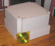
And I must say that would look pretty awsome for my taste! So some time ago I was almost sure to make this kind of a chassis ...
But ... Then I've figure it out - if in first case there was almost no space - in this version there would be a lot of unused space - so why not add also preamp in same chassis ...
BUT - than again - how to deal with buttons etc enough aestetically not to spoil clear lines too much ... Hmmm ...
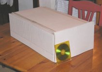
So I've decided to give another try - this time more classical - but because two 300mm heatsinks would be use per each side - that would mean more than 600mm in depth overall ... Hmm - and only 150mm height  That would look a bit strange ...
So I've decided to make a kind of golden ratio proportions - so the depth around 600mm, width 370mm and height 220mm ...
And that's what it came out:
But ... Then I've figure it out - if in first case there was almost no space - in this version there would be a lot of unused space - so why not add also preamp in same chassis ...
BUT - than again - how to deal with buttons etc enough aestetically not to spoil clear lines too much ... Hmmm ...
So I've decided to give another try - this time more classical - but because two 300mm heatsinks would be use per each side - that would mean more than 600mm in depth
overall ... Hmm - and only 150mm height That would look a bit strange ...So I've decided to make a kind of golden ratio proportions - so the depth around 600mm, width 370mm and height 220mm ...
And that's what it came out:
Attachments
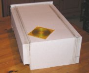
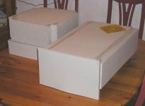
And a photo with both versions that are still "in play" before I make finnal decision - it just depends whether will I do Integrated Aleph (probably mix of A5' and AP 1.7 (maybe BZLS)) or power amp A5+ (the plus stands for a little bit higher biased version) ...
OH, BTW - both models are in ~1:1 scale ...
OH, BTW - both models are in ~1:1 scale ...
Attachments
wuffwaff said:is the stored energy of a power supply really important? ...capacitor size is the important faktor and not the voltage.
Hi William,
of course you are right
I just tried to explain the psu variations in Aleph amps.
(PS: Mine are loaded with 8x33mF/32V per monoblock)
Uli
Yes of course - in all cases I would taken care somehow for free air flow ...
Will see what will come out at the end ...
But I must say - after throwing some measurments and to the paper and calculated a bit how much $$ will I spend on Aluminium etc - I got pretty high number ... But than again - it's "the ultimate project" and I intedn to live happily for quite some years with him
diy heatsinks
Primoz,
I know nothing about your mechanical skills, but what about diy the heatsinks????
http://sound.westhost.com/heatsinks.htm
unfortunately the famous lotusblossom site seems to be offline, there was a complete plan for diy heatsinks
Uli
Primoz,
I know nothing about your mechanical skills, but what about diy the heatsinks????
http://sound.westhost.com/heatsinks.htm
unfortunately the famous lotusblossom site seems to be offline, there was a complete plan for diy heatsinks
Uli
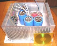
Hmm - tonight I've decided to try figure out with "real" parts ...
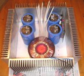
First thing was - I've decided to try it out with not so mirrored interior layout as I wanted it till now - and the result is I might squeeze everything into basic a little original A3 look-a-like chassis - so on this picture you can stereo PCB (but I will have to cut it to halfes) and PSU parts ... And a kind of internal layout that would work it out I think:
First thing was - I've decided to try it out with not so mirrored interior layout as I wanted it till now - and the result is I might squeeze everything into basic a little original A3 look-a-like chassis - so on this picture you can stereo PCB (but I will have to cut it to halfes) and PSU parts ... And a kind of internal layout that would work it out I think:
Attachments
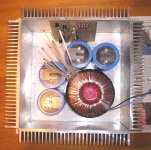
And view from up - the idea is:
PCB cut to half - so each channel is mounted on one heatsink - in the photo that would be "North" & "West" ones - but transistors would be mounted 3 per heatsink - so I would spread them equally - so there will be some wiring job ...
I have some thought about trannie - probably it would be a good idea to shield it with some "magnetic material" ...
Attachments
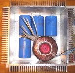
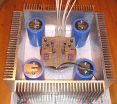
Ofcourse the rear heatsink will have to sacrifice few fins to get place for connectors ...
But for 230V, fuse connector and for power switch I had in mind to place them to bottom - as near as possible to trannie ...
btw - my first plan was to make it with centralized trannie ... But I guess it's better to have capacitors closer than in this case:
But for 230V, fuse connector and for power switch I had in mind to place them to bottom - as near as possible to trannie ...
btw - my first plan was to make it with centralized trannie ... But I guess it's better to have capacitors closer than in this case:
Attachments
- Status
- This old topic is closed. If you want to reopen this topic, contact a moderator using the "Report Post" button.
- Home
- Amplifiers
- Pass Labs
- A cross between A5 and A3