Hey All,
This is my first post here but I have spent quite a bit of time reading up on these forums and gain incredibly valuable information. I have decided on an amp that I want to build and will be building a stereo LM3886 amp from chipamp.com
I order the chips and boards from chipamp.com and sourced parts from across the web. I feel that I have the opportunity to make a pretty awesome amp for myself but of course only time will tell. Before I begin I have a couple of questions for those of you out there that can answer.
I am trying to build a nice amp without breaking the bank so no shortcuts but not overindulgences. It will be an integrated amp with an attenuator or pot and 3 way selector switch. I will likely be attaching a Sony 6 Disc CD player, iPod/laptop(1/8 to RCA) and a turntable with separate pre-amp.
1. Solder: I have read on here that the 37/63 mix solder is highly recommended but in what diameter is best for the mainly PCB soldering in this amp?
2. Internal Wires: Seems to be a big range here and I would like to keep my costs as low as possible. I have heard talk of Cat 5 cable. Seems like this would be nice as it is cheapish and colorful. Should I use different cable for different components?
3. Attenuator: What value would be best for this set up. I have read 10k from some 25k from others and 50k. The wiring of this will be similar to Peter Daniel's integrated amp (i.e. not a powered pre amp stage).
4. LEDs: I was hoping to add input source LEDs up as I have purchase a 4 pole switch. Can you recommend a wiring method for this?
Thank you! I look forward to sharing my build with you as it progresses
1. Solder: I have read on here that the 37/63 mix solder is highly recommended but in what diameter is best for the mainly PCB soldering in this amp?
Not to thin, or you will be using metres of the stuff. Probably around 1.2mm diameter for general purpose use. If you work with surface mount parts then you need thinner, around 0.7mm. And use a decent iron (minimum 25watt) with not to small a bit or you will have trouble soldering larger parts that absorb the heat.
The proper answer is have a selection of solder wire gauges and a selection of tips for the iron.
2. Internal Wires: Seems to be a big range here and I would like to keep my costs as low as possible. I have heard talk of Cat 5 cable. Seems like this would be nice as it is cheapish and colorful. Should I use different cable for different components?
Choose the wire according to the need. Power supplies need fairly thick cable capable of carrying a few amps. Don't get hung up over cable choice... off the reel 5 amp flexible cable from a hardware store is fine, just strip the outer insulation off and use the insulated cores within.
Anything carrying mains, needs mains rated (for insulation safety) cable.
Keep signal leads short and used screened cable correctly grounded... grounding is where most DIY efforts fail. The amp should be silent... no hum etc.
3. Attenuator: What value would be best for this set up. I have read 10k from some 25k from others and 50k. The wiring of this will be similar to Peter Daniel's integrated amp (i.e. not a powered pre amp stage).
Lower is better as a general rule (10k minimum) as the pot forms a low pass filter in conjunction with any input capacitance that the wiper of the pot works into. Most modern source equipment has no problem working into 10 k. Older (DIN output, 70, 80's gear) might object and give very low output.
4. LEDs: I was hoping to add input source LEDs up as I have purchase a 4 pole switch. Can you recommend a wiring method for this?
Easy, you wire the spare "wiper" of the switch via a resistor to the positive rail of the amp (choose to give around 10milliamps for starters... depends on the LED's). You can discount the LED volt drop, so the resistor is Vsupply/0.010 in ohms. Each pole of the switch then goes to an LED and the LED cathodes are all tied together and returned to ground. If it's to bright increase the resistor. Many modern LED's are bright at under 1 milliamp so you will have to experiment to see what suits you.
I agree with Mooly, except the LED detail.
I would try starting at 2mA for brightness.
It is far easier to add resistor in parallel than try to snip and add a resistor in series. Just leave the resistor leads on the back side slightly long. These can be used to attach and detach an extra parallel resistor.
The formula becomes LED resistor = [Vsupply - Vled] / 0.002 ohms
eg Vsupply ~10V
Vled ~1.9V
Resistor value = [10-1.9] * 500 = 4050ohms, use a 3k9 or 4k3
Hello,
Thank you both for your quick and thorough replies. These are hugely helpful and am I very excited for my project to begin.
For clarification on the wires, is 5 amp cable what I am referring to as Cat 5 cable as shown here:
Category 5 cable - Wikipedia, the free encyclopedia
I really like the idea of this cable since there are many colors and its fairly cheap.
I'll have to read up on the grounding more as there are a lot of topics on it and it seems to be of utmost importance.
For the LED:
Sounds like its fine to draw power from V+. Should I do this as a spice in the wire? Maybe this will become clear when I get all the components in front of me.
Is the wiper you refer to just another one of the tabs? There are four per selection and I was thinking three would be in, out and ground.
So would I be taking a wire off V+ running it to the spare pin, running a wire from that to a resistor to the LED for that input and then a wire from the LED to the ground.
I drew up a real bad diagram in paint if you wanna take a look at what I am interpreting.
This is the switch I am using
CK1457 6.35X20.7MM 4PL 3 POS FLAT SHAFT Lorlin Rotary Switches
Thanks again for your help!
Thank you both for your quick and thorough replies. These are hugely helpful and am I very excited for my project to begin.
For clarification on the wires, is 5 amp cable what I am referring to as Cat 5 cable as shown here:
Category 5 cable - Wikipedia, the free encyclopedia
I really like the idea of this cable since there are many colors and its fairly cheap.
I'll have to read up on the grounding more as there are a lot of topics on it and it seems to be of utmost importance.
For the LED:
Sounds like its fine to draw power from V+. Should I do this as a spice in the wire? Maybe this will become clear when I get all the components in front of me.
Is the wiper you refer to just another one of the tabs? There are four per selection and I was thinking three would be in, out and ground.
So would I be taking a wire off V+ running it to the spare pin, running a wire from that to a resistor to the LED for that input and then a wire from the LED to the ground.
I drew up a real bad diagram in paint if you wanna take a look at what I am interpreting.
An externally hosted image should be here but it was not working when we last tested it.
This is the switch I am using
CK1457 6.35X20.7MM 4PL 3 POS FLAT SHAFT Lorlin Rotary Switches
Thanks again for your help!
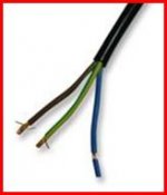
5 amp wire for PSU etc... see picture. Cat 5 is multicore and way to thin for the currents involved.
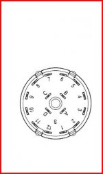
Switch... use your meter on ohms to identify the connections, a 4 way switch will have A,B,C,D "wipers" as shown and a 3 way, AB and C only.
Your link is to a four pole 3way switch") is that what you want ? or do you want a 3 way 4 pole ? First will allow you 3 audio inputs, the second 4.
is that what you want ? or do you want a 3 way 4 pole ? First will allow you 3 audio inputs, the second 4.
so anyway A and 1 connect and B and 4 and so on.Move the switch round a stop and it's A and 2 and B and 5 and so on. The 3 way will only have A,B, and C the 4 way will add another "D"
Switch... use your meter on ohms to identify the connections, a 4 way switch will have A,B,C,D "wipers" as shown and a 3 way, AB and C only.
Your link is to a four pole 3way switch
is that what you want ? or do you want a 3 way 4 pole ? First will allow you 3 audio inputs, the second 4. so anyway A and 1 connect and B and 4 and so on.Move the switch round a stop and it's A and 2 and B and 5 and so on. The 3 way will only have A,B, and C the 4 way will add another "D"
Attachments
I think the 4 pole 3 way switch is what I want since I only need to switch 3 inputs. I was reading on
gainchooser
about his passive preamp and it says
"For the 3-step switch I chose a simple model from Lorlin (UK) with 4*3 steps. That means I'm able to switch both channels AND the ground signal and still have one range of contacts left for future use, for example to switch LED's that indicate which channel is active."
Would my wiring diagram work for this? I'm no electrical engineer but it seems like the negative terminal of the LEDs need to connect back into the circut.
Thanks again for your help and patience
The LED's are wired like this using any of the 4 ways available eg A and 1,2,3,4 or D and 9,10,11,12 etc.
Switching grounds is something I haven't done on any of my designs... if you do this then you need to be sure that a ground is always present as the switch rotates to avoid very and possibly damaging "noises"... such as you get not fully inserting a phono lead/interconnect.
Edit... just reading your link on the preamp... I like the case post #31
http://www.diyaudio.com/forums/headphones/160646-germanium-single-ended-class-headphone-amp-2.html
Switching grounds is something I haven't done on any of my designs... if you do this then you need to be sure that a ground is always present as the switch rotates to avoid very and possibly damaging "noises"... such as you get not fully inserting a phono lead/interconnect.
Edit... just reading your link on the preamp... I like the case
post #31http://www.diyaudio.com/forums/headphones/160646-germanium-single-ended-class-headphone-amp-2.html
Attachments

Last edited:
Okay, making great progress here!
I got the boards and most of the components and soldered it all together. I am still missing a couple things-the case is the big one at this point. I am left with a couple more questions that I hope you all in the DIY Audio community can help with.
1. The LED in the BrianGT(chipamp.com)'s power supply board. I ordered just the board and need to get this LED. I know its blue but what kind of specs (voltage) does it have or is that unimportant?
2. For the LEDs to indicate input source, I appreciate all of the help to my noobish self. I am wondering the best way to attach them to V+. Can I just strip off some wire and loop them around or are there connectors for this? I assume I should be taking it off of the V+ rail after the transformer but should I take it off after the power supply board?
3. One more quicky. I have and IEC plug, fuse holder and switch. Would the order be (from main in). IEC plug, fuse holder, switch, transformer or IEC Plug, Switch, fuse holder, transformer. The switch is 20A rated.
Thanks! I'll try and get some pictures up of my progress thus far soon.
1. You can use any LED. You may have to adjust the resistor value, though.
2. You can just use any wire, but avoid loops. Keep it short and straight. It should be connected after rectification and smoothing, i. e. at or after the power supply board. The connection of the blue LED is a good indication, where to do that.
3. The fuse holder first, then the switch. That way you also have protection, if a wire comes off the switch.
So I've started my construction and finished the case today.
I've put together the amp up to hooking up the power supply board to the transformer. I turned it on and the LED (located on the circuit board) did not light up I began trying to check voltages of V+ and V- when I heard a loud pop. I quickly turned the amp off and found that a diode had broken.
What might have caused this? I feel like I did everything to this point correct but places I was a bit uncertain:
1. Hooking up to the Power Inlet plug. I went hot on the right side connector (looking at it from the side to witch it is soldered).
2. The LED may have been backwards.
I dont know what happened but its a major bummer and a bit frightening.
Think we need to see a picture... can't tell from description other than to say you have made some error somewhere.
Using a bulb in series with the mains saves major explosions and damage like this if you are unsure something is going to work.
If you have the circuit you are using showing the diode and it's location that would help too.
Using a bulb in series with the mains saves major explosions and damage like this if you are unsure something is going to work.
If you have the circuit you are using showing the diode and it's location that would help too.
you forgot to take the bulb tester off the shelf.I heard a loud pop. I quickly turned the amp off and found that a diode had broken.
What might have caused this?
Use the bulb tester for every new mains powered project and re-use it every time you modify or add anything to a project.
I always start by testing the transformer wiring, before I connect up the rectifier.
Hey all,
I'll make sure to use a bulb tester once I get a new rectifier so I dont cause any other damage.
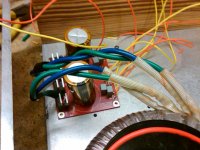
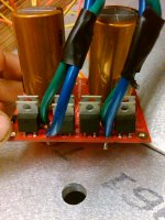
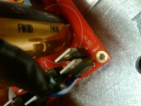
I have attached some pictures hopefully you can make heads or tails of them.
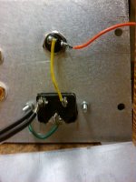
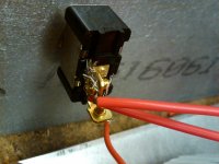
First is a picture of the mains plug area, second the switch in which the orange wire is that coming off the fuse holder in pic 1. Next two show my circut and boards and the last shows the diode. All of the orange and yellow wires were hooked up ahead of time and dont lead anywhere. I was just thinking that since I did have the board on risers yet it might have cause a short with the base.
I'll make sure to use a bulb tester once I get a new rectifier so I dont cause any other damage.
I have attached some pictures hopefully you can make heads or tails of them.
First is a picture of the mains plug area, second the switch in which the orange wire is that coming off the fuse holder in pic 1. Next two show my circut and boards and the last shows the diode. All of the orange and yellow wires were hooked up ahead of time and dont lead anywhere. I was just thinking that since I did have the board on risers yet it might have cause a short with the base.
Attachments
Is that a bit of burn on the base next to the rectifier (3rd piccy) ? Did it touch ?
Replace the diode/s check them all, then power up with a 60 watt bulb in series with the mains and make sure it's OK.
If so remember to discharge the caps via a resistor afterward (1 to 10 k 1 watt)
That wiring does look a bit scary
Replace the diode/s check them all, then power up with a 60 watt bulb in series with the mains and make sure it's OK.
If so remember to discharge the caps via a resistor afterward (1 to 10 k 1 watt)
That wiring does look a bit scary
I don't know if this applies but> Rather than wiring up everything and crossing fingers, you have more success by building and testing things in a logical sequence. XFMR > PS AC and DC > AMP DC conditions and offset > amp AC gain and freq response> thermal loading > etc
Firstly a dry run to get everything situated mechanically ie PCBs on standoffs, XFMR mounting. After the dry run, sometimes it makes sense to power things up sequentially separate from the chassis so most problems can be sorted out before permanent tidy wiring is done.
Identify power wiring and signal wiring and use appropriate gauge wires for each.
I'll try all the suggestions later today.
The wiring is a bit scary becuase I was just attaching it to the switch before mounting it to the panels. It will be fixed once the thing is done.
Definitely should have used a light bulb and will do when I try it again.
thanks for the help guys, I'll keep you posted as it progresses
The wiring is a bit scary becuase I was just attaching it to the switch before mounting it to the panels. It will be fixed once the thing is done.
Definitely should have used a light bulb and will do when I try it again.
thanks for the help guys, I'll keep you posted as it progresses
Finished the amp today. Thanks for all the advice I think I must have caused a short by letting it sit on the base. I still have the light bulb in and it lights up when the amp is turned on briefly and then throughout songs it gets brighter when the song gets louder. Is this normal and is safe to take out?
Thanks again, I'll post pics soon
Thanks again, I'll post pics soon
- Status
- This old topic is closed. If you want to reopen this topic, contact a moderator using the "Report Post" button.
- Home
- Amplifiers
- Chip Amps
- A couple quick questions as I begin my LM886