Well, since the dynamic CCS is gone it doesn´t qualify as an Aleph at all, but what do you guys think about this:
Edit: I forgot to draw a few things on the schematic.
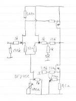
Output transistors are IRF9530/IRF530 with 220R gate stoppers, rails are +-12V and Iq=1,3A
Edit: I forgot to draw a few things on the schematic.
Output transistors are IRF9530/IRF530 with 220R gate stoppers, rails are +-12V and Iq=1,3A
Attachments
second version looks as safer bet ")
in both cases you need lag compensation across nfb resistor (15K ; 12K)
mebbe you can try with one range up-scaled nfb resistors (multiplied with 10) so you can use film cap in divider;
besides ,referencing bases of cascodes to intersection of two 47 ohms resistor is mebbe better........
besides besides-don't take me serious, I'm just toob boy
I´m not so sure that the cascode circuit is necessary, only the change from IRF9610 to BF245C (or some other Jfet) should decrease the input capacitance quite a bit I think.
When I get the time I´ll hardwire a prototype and see how simple it can get before losing performance.
When I get the time I´ll hardwire a prototype and see how simple it can get before losing performance.
Fuling said:My latest "invention":
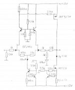
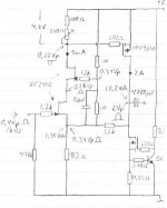
The AC and DC values are measured on a working prototype, not simulated. Max output voltage is 20Vp-p with 24V rail (missing in schematic).
nice
mebbe you can try dissimilar jfets for cascode?
mebbe you can try dissimilar jfets for cascode?
I must ask: For what reason?
I need all the current I gan get to drive the mosfet, and BF245C seems like a good choice. I tried BF245B at first but then I only got 5mA instead of 9mA.
The idea is great, but I looked at the curves for BF245C and it seems that the high current will be a problem.
The whole circuits operation point depends on the lower Jfet´s Vgs and Id.
The upper Jfet operates at -1,1Vgs, which seems way too low (as Vds)for the lower Jfet.
Though, I guess I´ll give it a try since I have a prototype setup, if it works it might be great!
The whole circuits operation point depends on the lower Jfet´s Vgs and Id.
The upper Jfet operates at -1,1Vgs, which seems way too low (as Vds)for the lower Jfet.
Though, I guess I´ll give it a try since I have a prototype setup, if it works it might be great!
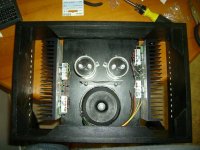
Since this version is more or less a prototype, I didn´t want to spend much work on a nice alu chassis (well, I gave it a try but it failed) so I decided to just put all the parts in a simple MDF box.
I ditched the cascode on the input stage sinceit was probably not necessary and besides, I ran out of solder points
I ditched the cascode on the input stage sinceit was probably not necessary and besides, I ran out of solder points
- Status
- This old topic is closed. If you want to reopen this topic, contact a moderator using the "Report Post" button.
- Home
- Amplifiers
- Pass Labs
- A chopped Mini-A with Jfet input stage