Here is more details:
...
Primary/Secondary thickness: I'm not entirely sure, as I wasn't given this information; but Secondary is VERY, very thick indeed. I had to trim the leads quite considerably before they would fit in the PSU board
Curious why you'd want thicker windings for the secondary without also boosting the thickness of the primary. Normally transformers are designed to share the copper losses equally between primary and secondary - having the losses mainly in the primary is just inefficient use of resources.
Electromagnetic shielding: It looks like metallised foil wrapped around the outside circumference of the transformer.
Is this equivalent to the band around the windings seen on some EI type transformer? I'd heard such shielding was unnecessary on toroidals as they have extremely low leakage flux.
Shielding between windings: It is an electrostatic screen between Primary and Secondary, connected to earth.
My guess is this enhancement is the single biggest reason for the sound improvements you've heard. It collects all the RF hash from the mains and diverts it to earth so it doesn't get onto your amp's ground. All toroids for audio should have one

Curious why you'd want thicker windings for the secondary without also boosting the thickness of the primary. Normally transformers are designed to share the copper losses equally between primary and secondary - having the losses mainly in the primary is just inefficient use of resources.
That manufacturer was originally using double runs of wires to create more thickness in secondaries; I had one such transformer and it didn't sound that good. I requested for my subsequent orders a single, thicker wire, and those transformers sounded better.
Using 400VA transformer with 40W chip amp puts you in a position where efficient use of resources shouldn't be anybody's concern
That manufacturer was originally using double runs of wires to create more thickness in secondaries
So did you compare with one that also had thicker primary? I'd expect further improvement but I have no experience of changing winding thickness on trafos myself.
Using a bifilar winding on the secondary (assuming that's what you mean by double run) wouldn't pack very well - might lead to increased leakage flux.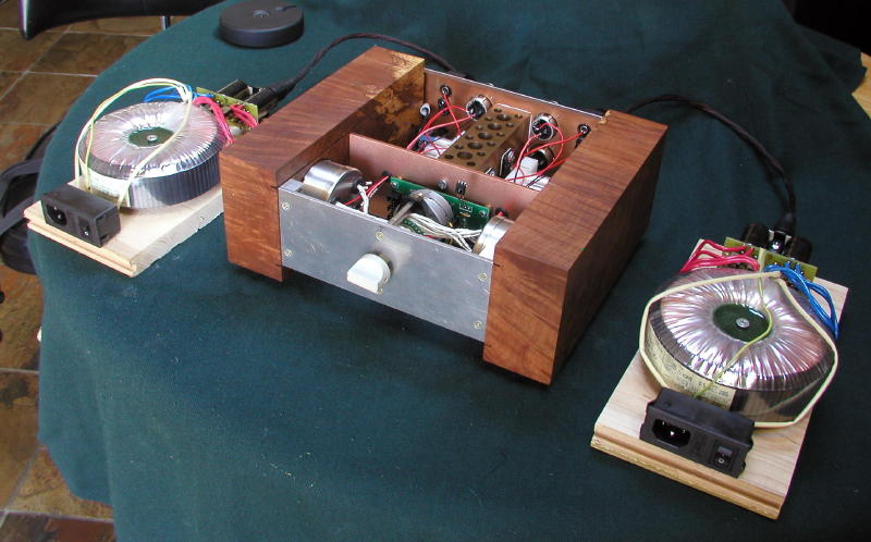
Why didn't I know this?...That manufacturer was originally using double runs of wires to create more thickness in secondaries; I had one such transformer and it didn't sound that good. I requested for my subsequent orders a single, thicker wire, and those transformers sounded better.
The one I got has double runs of wires on secondary...I guess one good news is that I can improve the sound further by just ordering a new one with single thicker wire...
I think we are all well past that stage!Using 400VA transformer with 40W chip amp puts you in a position where efficient use of resources shouldn't be anybody's concern
bifilar windings didn't sound as good as single wire.
I didn't explain clearly enough. I was curious to know if you'd listened to a transformer with both secondary and primary wound with a single run of thicker wire and compared its sound to one with just the secondary wound with the thick wire?
Why didn't I know this?...
I thought I sent you instructions where it specifically mentioned a single wire for secondaries:
TS300VA PRI:115V SEC:2x22V w wykonaniu AUDIO z rdzeniem z taśmy izopermowej,
- uzwojenie wtórne przy rdzeniu,
-50% większy przekrój drutu, drut pojedynczy (1,8mm)
After all, maybe the difference wasn't that big
I was curious to know if you'd listened to a transformer with both secondary and primary wound with a single run of thicker wire and compared its sound to one with just the secondary wound with the thick wire?
No, I didn't. However, since uncle_leon has bifilar windings on his transformer, for a purpose of experimentation, he can easily disconnect one wire run and see what difference it makes for thinner and thicker wire on a same transformer.
Last edited:
No, I didn't. However, since uncle_leon has bifilar windings on his transformer
He got bifilar primary windings too? Must have ended up looking a jolly lumpy transformer, not like your very smooth and svelte pancakes.
Easy, folks...
First, the trafo I have has bifilar windings on secondary only.
Second, it's not that easy to disconnect one wire run, because they are very solidly soldered together at both ends. And where they are not soldered together, they are enamelled, so it's impossible to solder to them easily...
Third, wouldn't thicker primary and secondary windings simply equal to higher transformer VA rating?
At any rate, it is still a damn good transformer!
First, the trafo I have has bifilar windings on secondary only.
Second, it's not that easy to disconnect one wire run, because they are very solidly soldered together at both ends. And where they are not soldered together, they are enamelled, so it's impossible to solder to them easily...
Third, wouldn't thicker primary and secondary windings simply equal to higher transformer VA rating?
Yes, and that's what I asked for in my order... I guess they must have missed that bit. I will probably buy another one with single wire secondaries, and ask for a discount because the first one was not precisely to order.I thought I sent you instructions where it specifically mentioned a single wire for secondaries
At any rate, it is still a damn good transformer!
Last edited:
First, the trafo I have has bifilar windings on secondary only.
OK, so then forget it.
Third, wouldn't thicker primary and secondary windings simply equal to higher transformer VA rating?
Probably not without an equivalent increase in the cross sectional area of the core. But its part of the way there, just as is increasing only the secondary thickness.
Hi,
Well, let me just suggest you think on this a little longer. There are reasons why you may want a lot of DCR in the primary and preferably lump a large chunk of the copper losses there. I actually prefer to derate the transformer power rating (based on the core anyway) and to specify lower flux together with a way above average DCR for the primary.
Then again, I also like to have a small airgap in the core and many other odd features. They usually make the transformer winders shake their heads in disgust and desperation how I can insist on so badly designed, so hard to wind, so inefficient and so expensive a transformer.
Torroidal Transformers have a lower leakage than EI Types, but it is not extremely low. A layer of Mu-Metal tape wound around the outside often does a heck of a lot of good.
Agreed all transformers (not just torroidal ones) should have one, but they are not the last or only improvement possible.
Ciao T
Curious why you'd want thicker windings for the secondary without also boosting the thickness of the primary. Normally transformers are designed to share the copper losses equally between primary and secondary - having the losses mainly in the primary is just inefficient use of resources.
Well, let me just suggest you think on this a little longer. There are reasons why you may want a lot of DCR in the primary and preferably lump a large chunk of the copper losses there. I actually prefer to derate the transformer power rating (based on the core anyway) and to specify lower flux together with a way above average DCR for the primary.
Then again, I also like to have a small airgap in the core and many other odd features. They usually make the transformer winders shake their heads in disgust and desperation how I can insist on so badly designed, so hard to wind, so inefficient and so expensive a transformer.
Is this equivalent to the band around the windings seen on some EI type transformer? I'd heard such shielding was unnecessary on toroidals as they have extremely low leakage flux.
Torroidal Transformers have a lower leakage than EI Types, but it is not extremely low. A layer of Mu-Metal tape wound around the outside often does a heck of a lot of good.
My guess is this enhancement is the single biggest reason for the sound improvements you've heard. It collects all the RF hash from the mains and diverts it to earth so it doesn't get onto your amp's ground. All toroids for audio should have one
Agreed all transformers (not just torroidal ones) should have one, but they are not the last or only improvement possible.
Ciao T
Hi,
you ordered a 22+22Vac transformer.
This almost certainly will be bi-fillar wound to ensure the two secondary windings have the same number of turns and the same length of winding.
Each secondary winding can be mono-filament, but high current windings require large diameter wire and it's easier to make each high current winding from bi or even tri-fillar wire.
Hi,
Well, you could go for full wave rectification fully independent for each rail and tie the rails together at the star ground. I like to use 150V/40A dual schottky diodes (not just because the result looks so much like a tube supply) for solid state supplies, together with double supplies. Try it one day.
Ciao T
Why didn't I know this?...
I guess one good news is that I can improve the sound further by just ordering a new one with single thicker wire...
Well, you could go for full wave rectification fully independent for each rail and tie the rails together at the star ground. I like to use 150V/40A dual schottky diodes (not just because the result looks so much like a tube supply) for solid state supplies, together with double supplies. Try it one day.
Ciao T
Well, let me just suggest you think on this a little longer. There are reasons why you may want a lot of DCR in the primary and preferably lump a large chunk of the copper losses there.
Haven't yet thought of one, so are you going to spill the beans oh trafo sifu? Or still running scared from people ripping off your ideas?
Torroidal Transformers have a lower leakage than EI Types, but it is not extremely low. A layer of Mu-Metal tape wound around the outside often does a heck of a lot of good.
Does it help fix up the asymmetry caused by the lead-out wires?
Agreed all transformers (not just torroidal ones) should have one, but they are not the last or only improvement possible.
Where would you fit one in an EI core or R core variant?
Hi,
Well, you could go for full wave rectification fully independent for each rail and tie the rails together at the star ground. I like to use 150V/40A dual schottky diodes (not just because the result looks so much like a tube supply) for solid state supplies, together with double supplies. Try it one day.
Ciao T
I'm not entirely sure what you mean by that... I can use full wave rectification with a single filament transformer anyway, can I not? Unless I'm missing something?... Well, I probably am, can you please explain?
I'm not entirely sure what you mean by that... I can use full wave rectification with a single filament transformer anyway, can I not? Unless I'm missing something?... Well, I probably am, can you please explain?
I also wondered. It probably means that each rail's supply comes off a centre-tapped winding - two separate centre-tapped windings for a bipolar supply. If this isn't what T meant it still sounds like a good plan for my next tansformer
Lots of wire but less diodes.Do you mean that each half-wave rectifier would be fed off its own transformer winding? I'm still a bit confused...I also wondered. It probably means that each rail's supply comes off a centre-tapped winding - two separate centre-tapped windings for a bipolar supply.
For the interested, here is some photos of the transformer connected to my testbed setup:
An externally hosted image should be here but it was not working when we last tested it.
An externally hosted image should be here but it was not working when we last tested it.
The transformer dimensions are 12.5cm diameter x 5cm height.
Where would you fit one in an EI core or R core variant?
If it's a split bobbin type, you don't really need one.
se
- Status
- This old topic is closed. If you want to reopen this topic, contact a moderator using the "Report Post" button.
- Home
- Amplifiers
- Chip Amps
- A chip-amp to rival Hi-End - design advice