
Thanks for the positive remarks guys. Tim - I know what you mean... I'm so glad I carried this one through to the end. So many designs end up in the bin.
Anyway, pics of the inside, and scope traces when I get a chance tonight.
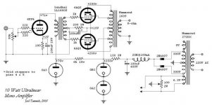
Attached is the updated schematic. Note that the resistor before the 0A2/0B2 combination has been lowered to 150 ohms. The higher value was causing the gas tubes to run too cool. Now they are at (approx) 15mA draw.
Anyway, pics of the inside, and scope traces when I get a chance tonight.
Attached is the updated schematic. Note that the resistor before the 0A2/0B2 combination has been lowered to 150 ohms. The higher value was causing the gas tubes to run too cool. Now they are at (approx) 15mA draw.
Attachments
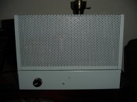
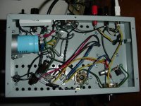
the insides
not much to look at - but notice the hardwired Nuvistor tied to the volume pot! It just hangs there. The sockets for these things are not only expensive, but poorly made and designed. I wouldn't bother if you've got decent eyes still and a steady hand.
not much to look at - but notice the hardwired Nuvistor tied to the volume pot! It just hangs there. The sockets for these things are not only expensive, but poorly made and designed. I wouldn't bother if you've got decent eyes still and a steady hand.
Attachments
performance
Well, so it should have been called "a 3.5 watt ultralinear..." Yup, I'm getting 3.45W RMS at clip. Not surprising since I have 235V on the plates of the 6AQ5's. But on the plus side, the frequency response is excellent.
@2.5W output, 1kHz Ref
20kHz -0dB
20Hz -2dB
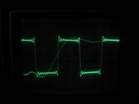
And with a 100Hz squarewave:
Well, so it should have been called "a 3.5 watt ultralinear..." Yup, I'm getting 3.45W RMS at clip. Not surprising since I have 235V on the plates of the 6AQ5's. But on the plus side, the frequency response is excellent.
@2.5W output, 1kHz Ref
20kHz -0dB
20Hz -2dB
And with a 100Hz squarewave:
Attachments
Rise time seems good. There is only a slight ring.
All in all I'm happy with the response for an amp with no feedback around the output transformer. I would like to work on the power problem though. The only alternative I see is going to battery bias to squeeze the extra 15V on the power tubes. This is the cost of the feedback inherent in UL, and the voltage levels set by the VR tubes I guess.
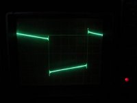
and the 1kHz squarewave...
All in all I'm happy with the response for an amp with no feedback around the output transformer. I would like to work on the power problem though. The only alternative I see is going to battery bias to squeeze the extra 15V on the power tubes. This is the cost of the feedback inherent in UL, and the voltage levels set by the VR tubes I guess.
and the 1kHz squarewave...
Attachments
 YEP no wonder Joe Rosen loves these tubes so much, they can take some punishment seeing as they are a miniature 7 pin device, he almost convinced me to rebuild my fisher x100a to use these tubes... on the plus side they are cheap[ relatively speaking and plentyful] even in NOS, SO WELL DONE
  & congrats on a well built amp , from what joe inferred in one of his posts these little tubes will run rings around almost anything in glass, should keep a copy of the circuit for myself... cheers to all
topcat...

I'd like to consider the circuit at the point now where we could begin to make improvements. Obviously the response at 100kHz sucks, but that is to be expected with a $30 transformer, isn't it?
Also, I forgot to mention that the residual hum I heard was 1.7mV RMS - just shows you how efficient the A-7's are...
And it looks really junky on the scope. Is it the VR tubes?
Suggestions?
Joel
Also, I forgot to mention that the residual hum I heard was 1.7mV RMS - just shows you how efficient the A-7's are...
And it looks really junky on the scope. Is it the VR tubes?
Suggestions?
Joel
And it looks really junky on the scope. Is it the VR tubes?
Dunno, if it is the VR tubes. However Gary Pimm uses a very small value to get rid of some junk...0,056uF. So do I but I don't have a scope to see if it helps...and can't hear the difference on my system either. Try it and see..
Would love to see scope pictures of before and after...

Cheers,
Bas
Oh yeah, I was gonna mention that sometime. Generally a small cap across a gas tube helps to filter out some noise. Obviously you don't want to go over the rated limit, .1uF for almost all cases I've seen, otherwise you turn your power supply into a relaxation oscillator, something a bit less than relaxing.
.047uF sounds about right.
In any case, that nasty ringing you got on your output, that's not gonna have anything to do with the reg... any idears about how reactive your test load was/is? Since it's ZNFB, you won't have as good damping as otherwise. Maybe a zobel network might help?
Tim
.047uF sounds about right.
In any case, that nasty ringing you got on your output, that's not gonna have anything to do with the reg... any idears about how reactive your test load was/is? Since it's ZNFB, you won't have as good damping as otherwise. Maybe a zobel network might help?
Tim
Sch3mat1c said:...any idears about how reactive your test load was/is? Since it's ZNFB, you won't have as good damping as otherwise.
Tim,
I was using a non-inductive 8 ohm, 20W resistor as my test load.
Bas,
I will try the small cap across the VR tubes tonight, and get back with the results.
And now I'm thinking that the power limitation MUST be due to the driver stage - because adding 15 extra volts to the plate supply will only get me to 3.9W RMS... of course I should've just checked to see if the Nuvistor was clipping - but I forgot to...

Thanks guys.
Joel
Dastardly digits!
That ringing on your 1kHz square wave looks distinctly digital. After all, you've got overshoot before the trailing edge of the square wave arrives - not something analogue can achieve. I'd be prepared to bet that your amplifier is a good deal better than you think. Was the square wave coming from a computer soundcard?
That ringing on your 1kHz square wave looks distinctly digital. After all, you've got overshoot before the trailing edge of the square wave arrives - not something analogue can achieve. I'd be prepared to bet that your amplifier is a good deal better than you think. Was the square wave coming from a computer soundcard?
Analogue: 1, digits: 0
Definitely. I predict that the ringing frequency along the top of the square wave is 19kHz. You are seeing the effect of all harmonics up to, and including, 19th reproduced at their correct levels, but nothing above that. If you test your amplifier with a cheap and cheerful function generator, it will look much better. The giveaway was the overshoot before the trailing edge.
Joel said:I was using my CD player and a CD test disc actually. So, yes, it was a digital source. Do you think that's the problem?
Definitely. I predict that the ringing frequency along the top of the square wave is 19kHz. You are seeing the effect of all harmonics up to, and including, 19th reproduced at their correct levels, but nothing above that. If you test your amplifier with a cheap and cheerful function generator, it will look much better. The giveaway was the overshoot before the trailing edge.
- Status
- This old topic is closed. If you want to reopen this topic, contact a moderator using the "Report Post" button.
- Home
- Amplifiers
- Tubes / Valves
- A 10W ultralinear amplifier with unique features.