thank you just a few minutes ago Mr. Miles told me that is possiblehi vargasmongo .it looks o.k it should work.
")
I found a errata on one of the bleeder resistor here is the updated file I might be wrong but I can see that there are two bleeder resistors connected on the same -120V spot is odd to me so I changed but the first files still the same so you can see what I mean
If you don't mind, maybe you can make another version with this diode.
Regards
Attachments
If you don't mind, maybe you can make another version with this diode.
Regards
I can do that sure
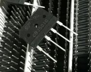
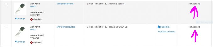
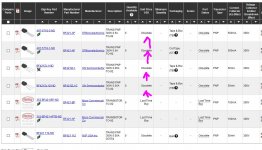
also yesterday I found out that the PNP transistor BF421 is obsolete and no longer available "they can be found on eBay well I rather change that" so I changed for KSP92 that have the same characteristics the only difference is the pins, the BF421 is E C B and the KSP92 is E B C so I have to update the PCB to accommodate the KSP92 and also MPSA92 can be use I will leave the update Sprint Layout 6 file here but, at the same time I will leave the original layout intact on the same fileAttachments
I can do that sure
I guess BF421 still produce by KEC Korea Electronic.
Why don't you design pcb for H900P, latest sch from Apexaudio?
It has more vas current and add vi limiter.
I guess BF421 still produce by KEC Korea Electronic.
Why don't you design pcb for H900P, latest sch from Apexaudio?
It has more vas current and add vi limiter.
oh I didn't know that there was a H900P is there a link of the layout PCB?
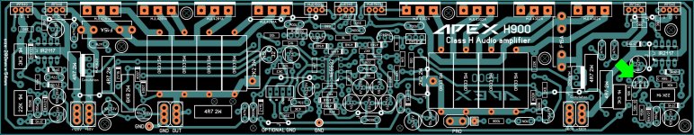
Apex 900 PSU with optional bridge rectifier GBJ5010
900W H-class PA Amp with Limiter
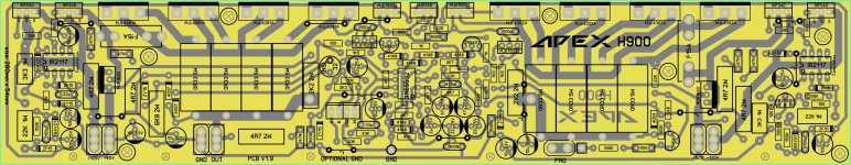
Seems Mile didn't share yet the bottom side, only top side.
is fine I understand him but at least I can try this one
hello guys question does Apex H900 need zobel+resistor coil or not?
Yes
Attachments
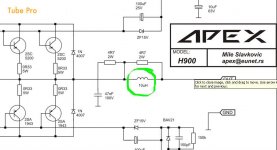
it does? wow I didn't not see that I think I can make a small PCB for that thank you hey, what schematic is that? can you post the whole schematic if not I understand
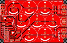
I spend a few hours tuning the layout look a lot better I thinkAttachments
Last edited:
it does? wow I didn't not see that I think I can make a small PCB for that thank you hey, what schematic is that? can you post the whole schematic if not I understand
I Vargasmongo, no I cant, because this is the only image tha I have
I Vargasmongo, no I cant, because this is the only image tha I have
is cool thank for replay about the zobel
regards
Juan
hi ya'll I decide to add the coil why not right? I'm not sure if this coil might be 10uH I think need to double the turns to double layer air coil I put some number and this can be a really expensive project to do but at least I have all the designs saved
I put some number and this can be a really expensive project to do but at least I have all the designs saved Attachments
it does? wow I didn't not see that I think I can make a small PCB for that thank you hey, what schematic is that? can you post the whole schematic if not I understand
pls share me email layout ax 14 clas h sir send me email cah.galaow@gmail.com
sorry I send wrong layout you say AX-14 why? we are on Apex H900 design not 14 clas hpls share me email layout ax 14 clas h sir send me email cah.galaow@gmail.com
Last edited:
sorry I send wrong layout you say AX-14 why? we are on Apex H900 design not 14 clas h
ax-14 clas h sir pls send me
ax-14 clas h sir pls send me
sorry I don't have it please keep subject of Apex H900 only that is what I'm doing
I'm confused about top rail comutation mosfets
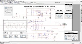
Hi I think this might be the lat post about me studies of the Apex H900 and I was able to simulated and works really well a lot more power than what I really need it is capable of give more than 1200W to 4 ohms load the THD is high after it reach 1250W about 0.6% THD not bad I think the only thing that got me confused is that the +HV 120V the mosfets orientation the simulation results is weird if I place the D drain to +HV120 to be honest I'm not so familiar with mosfets so will this does not matter? I really don't want to made a mistake and change the layout clone I did if that does not matter please let me know
I think most be the simulation but I want to be sure
Hi I think this might be the lat post about me studies of the Apex H900 and I was able to simulated and works really well a lot more power than what I really need it is capable of give more than 1200W to 4 ohms load the THD is high after it reach 1250W about 0.6% THD not bad I think the only thing that got me confused is that the +HV 120V the mosfets orientation the simulation results is weird if I place the D drain to +HV120 to be honest I'm not so familiar with mosfets so will this does not matter?
I really don't want to made a mistake and change the layout clone I did if that does not matter please let me know I think most be the simulation but I want to be sure
Attachments
Last edited:
- Home
- Amplifiers
- Solid State
- 900W H-class PA Amp with Limiter