It's my 8th channel of h900
I got it
Now the problem solved
But where is sir mile?
??
I started too many threads already, and this will bring me more questions to ansver, all this just take to much my free time. I will share new projects next year.
Regards
waiting for new project.minimum 1500w and maximum 2500w.
mr mile i've made your ultimate protection (PA protect)so far it's good i tested dc detect at 1.5 volt relay disengage and re-engage quickly however the protect led is not as good i expected but not an issue, what i want is can we adjust the high speed fan 45-50 degrees instead of 60 degrees? and the rest is ok. thanks mile.")
sir mile, i have a question about your design of pa protect for B500/H900. i've seen there's a difference between the schematics and the layout pcb that you've made. the difference is the diodes polarity (4148), i had marked with red ellips on both pics. my question is, which one is the correct polarity (4148)? the schematics or the layout?
Attachments
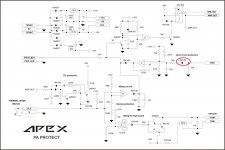
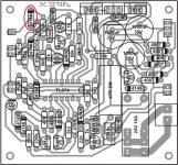
sir mile, i have a question about your design of pa protect for B500/H900. i've seen there's a difference between the schematics and the layout pcb that you've made. the difference is the diodes polarity (4148), i had marked with red ellips on both pics. my question is, which one is the correct polarity (4148)? the schematics or the layout?
PA Protect component layout.
Attachments
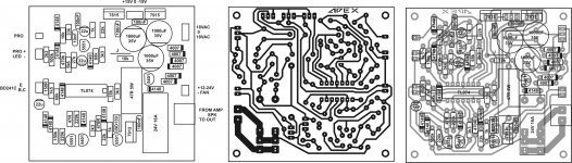
PA Protect component layout.
Thanks for your answer sir
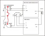
I have a question about bridge mode , i've found a schematic on the internet about bridging this amplifier , my question is when according to this schematic the channels are bridged the signal input comes only from one channel not from both at the same time , but since bridge is meant usually to drive a high power speaker in mono mode shouldnt there be another switch that switches together both inputs A and B?
Attachments
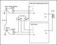
no my idea was different yes I have signal coming into one channel while the other receives the inverted signal from the first channels OP.
the question was about whether I can simply connect the both incomming channels before i feed them further down into the channel A mono bridge mode.
see illustration in the attached schematic.
thanks.
the question was about whether I can simply connect the both incomming channels before i feed them further down into the channel A mono bridge mode.
see illustration in the attached schematic.
thanks.
Attachments
hi apex sir,
can h900 load 2 ohm with tef sch?
how many output pairs for 2 ohm load?
how many watts for 2 ohm load?
you are crazy about 2 ohm amp but the fact is 2 ohm topology is different.yes you can do this by adding more pair but you will never reliable while playing 2 ohm load with diy version.there should be output current control circuit which block the follow of current in 2 ohm.In these amp specification if power is 1000w in 4 ohm it will be 2000w in 2 ohm but in professional specification it will be 1300w into 2 ohm.
I have a question folks, I built my smps for this amplifier which I finished back during high school.
when i connect it it sounds weird , first of all there is a 0.12 volt bias on both channels which when a speaker is attached is audible as a low frequency HUM , could be around 50hz, sort of similar to the typical mains hum when using an old transformer but since i'm running an smps I doubt this low hum could come from it.
also one of two channels has very bad distortion when playing music, the other one has only minor distortion.
the thing that i find quite weird about this amplifier is that on many of the layouts it's signal ground isn't connected to the actual ground at any place, nor the ne5532 is referenced to ground at any place.then at some other schematics that have been laid out here i find a 100nF capacitor going from the signal ground to the actual ground but shouldn't it also have some low value resistor ?I mean where is the reference for the op amp to ground when using simply a low capacity capacitor?
Shouldn't there be some 68k between signal input and signal ground , and then some very low resistance between signal ground and the actual ground ?
Last edited:
Forgot to mention one thing, back when I made the amp boards I didn't get the NSL32 optoresistor, so i soldered in a clip indicator LED and left the twp pins between input and input ground empty , I assume there needs to be a resistor added so that the input signal would have a reference to its ground correct?
What should be the value of the resistor to use there?
What should be the value of the resistor to use there?
Forgot to mention one thing, back when I made the amp boards I didn't get the NSL32 optoresistor, so i soldered in a clip indicator LED and left the twp pins between input and input ground empty , I assume there needs to be a resistor added so that the input signal would have a reference to its ground correct?
What should be the value of the resistor to use there?
Go to post #215
With all respect Mr.Mile, why then in your circuit schematics one of which I have it doesnt show like this?
some of them have no ground reference for the signal showed at all , some only show a capacitor to ground ?
I do understand that there should be a more proper connection like the one you showed in #215 but I think this is sort of messing up peoples heads.
I will rewire the boards tomorrow and see how that goes , as for the missing NSL32 part could you also point out what value resistor should I better put in there ?
Thank you.
- Home
- Amplifiers
- Solid State
- 900W H-class PA Amp with Limiter