I have a vintage Hammond Power Transformer with a 450-0-bt-450. I think I measured 50 something on the bias tap. A 5v pair and 6.3v pair. I don't know the current rating, but it's big enough to anchor an aircraft carrier, so I should be ok.
I have done many 5e3, jtm45, champ, Princeton, dumble clones. What can I do with this thing? Any suggestions? I wanted to do a 6G2 Princeton Reverb or similar, but I think this is too much.
Thanks for any ideas!
Chris
I have done many 5e3, jtm45, champ, Princeton, dumble clones. What can I do with this thing? Any suggestions? I wanted to do a 6G2 Princeton Reverb or similar, but I think this is too much.
Thanks for any ideas!
Chris
Well, depend on what you want to spend on output tubes and iron. But one suggestion would be EL34 PP, nice tubes that can do much with the about 630 volts that the DC after rectificaton with SS diodes would give. Have not looked up the figures, but this would get you a lot more than 50 watts, with an OPT of about 5-6 kohms P-P.
BTW, if your question is about guitar amps, then this is not the right forum. Here we discuss HiFi")
BTW, if your question is about guitar amps, then this is not the right forum. Here we discuss HiFi
Last edited:
Hammond hasn't changed their parts since the 1950s. Try to look it up. Weigh it and find one of the same heft. Knowing the current will set some outer limits what is practical. But if it really came off an aircraft carrier, it may be for a kiloWatt radio ham rig.
Several tubes will stand >600V on plates. Very very few are rated for near that much on screens. Since screen current is very variable we can not take a large drop in a dumb resistor. True, even back in the 1970s it was possible to rig a TV transistor and 300V Zener string (selected 1N914) as a solid G2 supply.
Several tubes will stand >600V on plates. Very very few are rated for near that much on screens. Since screen current is very variable we can not take a large drop in a dumb resistor. True, even back in the 1970s it was possible to rig a TV transistor and 300V Zener string (selected 1N914) as a solid G2 supply.
Would be nice to have tube amp in the office
That would be nice
But also that would be much to much for having for background music during work. No, that transformer is for doing heavier work, at high volumes 300V Zener string (selected 1N914) as a solid G2 supply.
That was interesting. But how many 1N914 was needed to find the right ones? And is 1N4148, which is the common equivalent, equally usable?
That concept and the OP's 450-0-450 doesn't "jive" with Hammond's product chart. The 278X and 279X come close. Neither of those items will produce the current needed to support a stereoblock using EL34s or 6L6GCs, when cap. I/P filtration is employed. A possible stereoblock using a 278X would employ PPP 6Π14Π-EB (6p14p-ev), AKA EL84M, "finals" and a SS rectified choke I/P filter B+ PSU. Being able to access the full VA capability of the power trafo contributes mightily to the cause. Voltage multiply the 5 VAC winding to derive the bias (C-) supply.Hammond hasn't changed their parts since the 1950s.
If you can weigh the transformer and also measure dc resistance of each winding, we should be able to better guess current ratings based on other transformers.
Also, remember when measuring the HV winding, you can get flyback voltage spikes if you are holding the windings in your hands while attaching the ohmmeter leads. It is sometimes a little fun or maybe to avoid.
Also, remember when measuring the HV winding, you can get flyback voltage spikes if you are holding the windings in your hands while attaching the ohmmeter leads. It is sometimes a little fun or maybe to avoid.
I will record resistance and voltages in the morning, along with physical dimensions. I have some paint to remove from one of the end bells to get at the manufacturer codes. I assumed it was hammond, being removed from a hammond organ/Leslie amp chassis....but you know what they say about assumptions.

I apologize for the delay and I appreciate all of the responses.
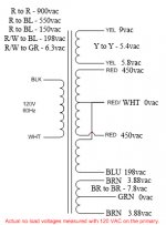
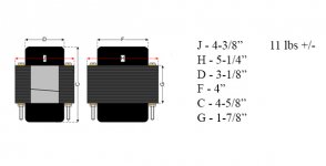
I noted some anomalies with voltages. I may be making assumptions to what is and is not a center tap, so I have shown all the voltages that I could think of testing. Hopefully this will help shed some light on what this is. I have yet to scrape the paint off to reveal the code, so I may run back out and do that in a moment or two. Attached are the voltages and dimensions. My shop scale is dead. I used the bath scale, so it may not be super accurate.
Thanks, again, everyone. You are all very much appreciated.
Chris
Attachments
I apologize for the delay and I appreciate all of the responses.
I noted some anomalies with voltages. I may be making assumptions to what is and is not a center tap, so I have shown all the voltages that I could think of testing. Hopefully this will help shed some light on what this is. I have yet to scrape the paint off to reveal the code, so I may run back out and do that in a moment or two. Attached are the voltages and dimensions. My shop scale is dead. I used the bath scale, so it may not be super accurate.
Thanks, again, everyone. You are all very much appreciated.
Chris
My noted "BL" was supposed to be "BLU"
Nicely done charts.
The pictured relationship of Blu to RED/WHT is an impossibility.
On the Yellow winding lead the marked 5.8VAC measurement was from where?
The voltages from each end of RED winding to Blu don't add up to the RED to RED VAC so something is off there too.
Did you take resistance/continuity measurements as well?
Few odd results as pointed out above, but looking at it YL - YL is your 5v rectifier valve wndg, Rd-Rd HT/B+ with Wh - center tap, the blue looks like a mistake, should be joined to the bottom red HT wndg and is presumably your negative fixed bias, Br - Br is your htr wndg.
You really need to know the current/load ratings. Have you any big resistors? Try a 2 ohm 50w (dummy load?) for the 5v, a 4 - 5k or two 10k 50W in parallel for center tap to one 450v and a big 50w 1k5 for the 6.3v htr wndg. If those resistor values result in no much voltage drop, that should indicate, 5v @ 3A, HT/B+ @ 180 - 200mA and 6.3v @ 4A. These being approximate values. You can use smaller wattage R's, but you'll have to be quick.
If you can measure the core area this software will give you an estimate of your tfmr's VA/W rating and you can put in what you think your winding current ratings maybe to see if your guess is right.
Sorry, I forgot to link in tfmr software - Transformer Calculation Software | Electronic Circuits
- Status
- This old topic is closed. If you want to reopen this topic, contact a moderator using the "Report Post" button.
- Home
- Live Sound
- Instruments and Amps
- 900v ct PT - What to build? Suggestions please ;)