Agreed ") , but I wanted to try since the following 8(sic!) op-amps fed by the dac out should already limit the band and residual upsampling artifacts.
, but I wanted to try since the following 8(sic!) op-amps fed by the dac out should already limit the band and residual upsampling artifacts.
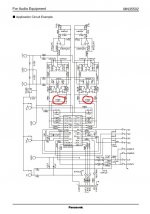
BTW while the application example suggests a 330pF, the board sports 470pF.
I'll test and report, but first I'm also going to change the 1.5uF ceramic (go figure, on the schematics they were referred as 1.5MF) caps between the 4 analog/digital supply rails to the DAC, with film caps.
, but I wanted to try since the following 8(sic!) op-amps fed by the dac out should already limit the band and residual upsampling artifacts.BTW while the application example suggests a 330pF, the board sports 470pF.
I'll test and report, but first I'm also going to change the 1.5uF ceramic (go figure, on the schematics they were referred as 1.5MF) caps between the 4 analog/digital supply rails to the DAC, with film caps.
Attachments
Looking at that and I would definitely leave those in place.
It might be worth looking at using JFET opamps for that first group because they are less likely to have non linearity issues than bjt types should any HF noise and hash be present. Your player may already use them of course.
It might be worth looking at using JFET opamps for that first group because they are less likely to have non linearity issues than bjt types should any HF noise and hash be present. Your player may already use them of course.
Thank you Mooly,
I doubt it already uses them: on the op amps I read 4580DD JVC 30568.
On NJM-4580DD NJR Audio Amplifiers | Mouser Europe, I read bipolar technology.
I doubt it already uses them: on the op amps I read 4580DD JVC 30568.
On NJM-4580DD NJR Audio Amplifiers | Mouser Europe, I read bipolar technology.
Attachments
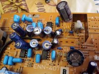
The 4580 is a common bipolar device. Those could definitely be worth experimenting with... fit sockets and try some alternatives.
LM4562, about as good as it gets but still bjt.
TL072, FET input don't believe all you read... listen yourself.
TLE2072, FET input. The 'upmarket' TL072 with better drive ability.
OPA2134 or OPA2132, FET input. I don't like this these but they are well regarded by many.
LM4562, about as good as it gets but still bjt.
TL072, FET input don't believe all you read... listen yourself.
TLE2072, FET input. The 'upmarket' TL072 with better drive ability.
OPA2134 or OPA2132, FET input. I don't like this these but they are well regarded by many.
...JFET circuits like, for example, this one?
http://lampizator.eu/LAMPIZATOR/FETISHIZATOR/JFET_CDout.pdf
I'll look for the TLE2072, I seem I saw them on Mouser this morning.
Thanks a lot, as usual!
http://lampizator.eu/LAMPIZATOR/FETISHIZATOR/JFET_CDout.pdf
I'll look for the TLE2072, I seem I saw them on Mouser this morning.
Thanks a lot, as usual!
I hadn't seen that circuit before, but yes, that basic configuration is the kind of thing to try. It will colour the sound somewhat like a common cathode stage would.
They are the sort of circuits you can quickly knock up to see if you like the effect, but in your case I would just try the opamps first.
They are the sort of circuits you can quickly knock up to see if you like the effect, but in your case I would just try the opamps first.
Thank you Mooly,
...waiting for some fresh elco and tomorrow I'm going to buy the TLE2072 replacement for the 5 4580 around. Should start practising with desoldering op-amps.
Being on Mouser, I'm looking for best Q/P ratio for substitutes of the tiny 1.5uF ceramic supplying the DAC... Wondering if any MKP safety film cap might be fine...
I find solder braid the best for removing parts. They should come out in seconds with zero damage to both print and the old parts.
The four 1.5uF caps in your diagram above all seem to be extra decoupling across larger electrolytics. If those are the ones you mean then ceramics are a good choice.
The four 1.5uF caps in your diagram above all seem to be extra decoupling across larger electrolytics. If those are the ones you mean then ceramics are a good choice.
So it's time to buy some solder braid, I must say I never loved much the (de)soldering pump. Yes. the 1.5uF caps are extra decoupling near the DAC, in parallel to (moderately) larger electrolytics. I already beefed the elco up, with higher voltage ratings but was wondering if it might be the case to improve them: on the 1541 I seem I recall the general consensus was to exchange the ceramics with MKP or CDE polymeric.
Thank you as usual for sharing your time!
Thank you as usual for sharing your time!
- Status
- This old topic is closed. If you want to reopen this topic, contact a moderator using the "Report Post" button.
- Home
- Source & Line
- Digital Source
- '90 jvc xl-z574: often "00" TOC displayed