That looks nice, I did an 832 PP amp using 6j5 to drive it and a self inversion based on the simple EL84 amp of Yeo at diyparadise.com. It sounds great.
I also tried 5670 driver as used by ultranalog.com, too much gain and also the 12at7 of audiohobbyist.com and this have more gain the 5670. Between the 5670 and the 12at7, i will go with the 5670, more neutral.
I also tried 5670 driver as used by ultranalog.com, too much gain and also the 12at7 of audiohobbyist.com and this have more gain the 5670. Between the 5670 and the 12at7, i will go with the 5670, more neutral.
Hi there,
Well, unfortunately the site is in dutch (still working on translating) but the pictures should be nice for you guys: http://www.macrovisioned.net.
The GU32 project actually is the same as this 832a amp stuff.
Check it out, and if you want you can always leave a message in the guestbook (-:
Well, unfortunately the site is in dutch (still working on translating) but the pictures should be nice for you guys: http://www.macrovisioned.net.
The GU32 project actually is the same as this 832a amp stuff.
Check it out, and if you want you can always leave a message in the guestbook (-:
There's also this
http://www.platenspeler.com/diy/headphone/uk_martian_1.php
http://www.platenspeler.com/diy/headphone/uk_martian_1.php
Hi-as the driver tube gain on my version is too much i decided to try removing the 12AT7 valve and associated components.
I had intended to use my World Designs Pre 3 preamp through a transformer phase splitter,but was advised to try "cathode coupled phase splitter". This involves feeding the pre amp output to one of the 832A grids and the other grid to ground,which seemed a crazy thing to do BUT it works !!
Sound quality in my system is a bit more open,and i have enough volume with my VoFos speakers (Fostex 206).
Technical description from Nick Goreham on Audio-Talk on how it works with the CCS i have on the cathodes.
"If you imagine the setup, both cathodes tied together with a resistor (for the moment) to ground, equal anode loads (resistor or primary of transformer), signal into v1 grid, v2 grid to ground.
Apply a 10v signal to the v1 grid. If only that cathode was connected to a resistor to ground, you would have a cathode follower, so the voltage on the cathode would move to track the grid, minus a small amount, as the gain of a cathode follower is less than one.
But because the cathode resistor is shared, v1 is trying to move the cathode resistor voltage to just below 10, v2 is trying to keep it at 0v (grid tied to ground), so between the two, the cathode ends up just below 5v.
Now remember the valve only knows the voltages and currents on its pins, so one triode sees its grid at +5 with respect to its cathode, and the other seeis its grid at -5v WRT its cathode. So there you have the phase splitting, one see the -ve of the other.
What we described here is a comon cathode, or cathode coupled phase splitter. Adding the CCS just forces the system into closer balance, and removes the "just less than" parts in the above description."
Philip
832a PP amplifier - update
Hello,
This is just a reminder and an updating of an earlier posting. I moved the pictures of my 832pp to another ISP.
--------------------------------------------
I build a 832pp based amp from this schematic in 2007. It was my first amp! I'm still very impressed and happy about the sound of it. Quite powerful and lots of air on sound stage.
http://www.audiohobbyist.com/projects/832.htm
The only modifications I did :
- Upgraded filter cap to 2900uf - 400 V
- Add a serial resistor and switch for slow charging of the filter cap
- Add a switch and parallel resistor for filter cap discharging at shutoff
- Add a switch for power on (after charging)
- Add a separate transformer, voltage regulator and filter cap for 12AT7 filaments.
- I used a Hammond 261M6 transformer for PSU.
Nice project to work on. Great sound for the price! Go for it
For a few pics of it :
http://pelfra.host56.com/832pp/index.html
Francois
On mine I used an Antek AN - IT200 which has twin 200V & 6.3V secs so you can make the power supply almost dual mono.
My amp now sports a 12A 5V triode as driver and has the output cap coupled to one 832a grid, with the other grid grounded. This saves the need for a phase splitter. Simple, and it works.
I was thinking of using an anode choke on the 12A but a friend has suggested a CCS supply instead.
Still considering that idea.
I´ve finished bread-boarding my 823 amp now based on the Audiohobbyist schematic. I´m getting B+ of 303v without the tubes in, falling to 285 v when its playing. It worked without any problems, as soon as I had soldered some bad turretboard connections. I am worrying that the B+ might be a bit high.
Do any of you 832 builders out there have any comments?
Maybe use tube rectifiers to bring down the voltage a bit, But I don´t have a center tapped PST.
Do any of you 832 builders out there have any comments?
Maybe use tube rectifiers to bring down the voltage a bit, But I don´t have a center tapped PST.
Last edited:
trondareo,
If you want to bring the voltage down a bit use a hybrid bridge: ie first 2 diodes solid state, then a tube for the remaining two. If you use an octal socket you will have a wide range of rectifiers to try to get the drop you desire.
Do a search under 'graetz bridge' for more info (this is the popular but incorrect term for a hybrid bridge).
Last edited:
Hey Thanks, mach1
I am just back from two days of skiing in Sweden. This was an interesting idea. I found a circuit at Lundahl Transformers. Now to start the search for a suitable rectifier tube.
I´ll post the powered voltages tomorrow, hoping someone can give me some help on deciding If I am Ok or how much I should bring them down.
Are these voltages reasonable?
It seems to me that 12AT7 unit one has a very low plate voltage.
12at7 unit one
pin6: plate 52v
pin7: grid 0v
pin8: cathode 1v
unit 2 splitter
pin 1: plate 216v
pin 2: grid 52 v
pin 3: cathode 57v
GU32 (832A)
pin 2: 1v
pin 3: 256v
plate2: 277v
pin 4: 20v
plate1: 277v
pin 6: 0,1v
It seems to me that 12AT7 unit one has a very low plate voltage.
12at7 unit one
pin6: plate 52v
pin7: grid 0v
pin8: cathode 1v
unit 2 splitter
pin 1: plate 216v
pin 2: grid 52 v
pin 3: cathode 57v
GU32 (832A)
pin 2: 1v
pin 3: 256v
plate2: 277v
pin 4: 20v
plate1: 277v
pin 6: 0,1v
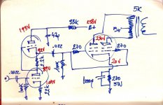
You show 270 ohm to grids of the 832A (as stoppers? I usually think of 1k-1.5k for stoppers...). Do you mean as stoppers to the 6SL7s? I see no stoppers there, just grid leaks. Or do you mean grid leaks to the 832As? Also, the 6SL7 cathode bias isn't bypassed. Is that correct?
I haven't built my 832A yet as I have a ton of other more pressing projects, and I don't typically have comments for a design until I've built it. But press on, and please post your design comments as you do.
I haven't built my 832A yet as I have a ton of other more pressing projects, and I don't typically have comments for a design until I've built it. But press on, and please post your design comments as you do.
I´ve changed the grid stoppers to 1k,bypassed the cathode resistor from 6sl7 with 200u.(because I had one lying around)
Two options for grid 2 of 832a:
1/a 100ohm g2 resistor reads 250v,234v to plate,21.9 at cathode.if my maths are correct I have 81ma=17.2w plate dissipation
2/10k g2 resistor reads 215v,244v to plate,18.8v at cathode.69ma=15.68w.
the data from 832a shows different max ratings but I´m a bit lost at that point.
Sound is well balanced and absolutely hum free...
1- no phase inverter for push-pull operation.
I wondered about that too. I've seen threads about people trying to run the 832A single ended, but that hasn't worked at all.
Your schematic seems incorrect. Two obvious points:
No "seems" about it. That schemo can't work since the plates of the finals are in opposition, and will null out. The only signal you'd get would be what little got through due to final/OPT imbalances.
Looks like he fouled up a schemo for a SE final, with the dual tetrode sections paralleled and pseudotrioded.
In addition, I'm curious as to how the driver stage is supposed to work. The lower tube has a cathode current of some 0.47mA, while the upper tube passes about 1.3mA through its cathode. The voltage over the 33k resistor suggests that the ensemble somehow draws about 1.9mA.
gja, what are you trying to achieve with this circuit? Why wouldn't you just build one of the circuits in this threads that are proven technology?
gja, what are you trying to achieve with this circuit? Why wouldn't you just build one of the circuits in this threads that are proven technology?
Coupling cap and input cap values seem awfully low to me too... But I'm curious about a built version sounding good. Miles' comment about the finals seems right to me, though I'm a bit weak on the fundamentals. Sure seems like it's kinda push-push, and couldn't really work.
So that has me curious. A working prototype based on a schematic that can't work? What's wrong in this picture? I'd love to know.
So that has me curious. A working prototype based on a schematic that can't work? What's wrong in this picture? I'd love to know.
- Home
- Amplifiers
- Tubes / Valves
- 832A Push Pull 5W