Another confusing problem has made itself visible, I scoped accross the load on the secondary of the OPT and found clipping occured at 20V peak into 10ohms, I was expecting to see it clip at more like 39V?
I can see the 807 grids go to 50V peak before clipping which is easily enough to drive them fully on (data sheet quotes 86V grid to grid, this equates to 100V grid to grid!).
HT drops from 520V no signal to 425V (well into clipping). The drop in HT has no effect on the fixed bias voltage or any effect on the preceding voltage amplification stages (i checked with the scope).
Yet again im beat :/, cant see any oscillaltion which is good though, so cheers for helping me with that problem!
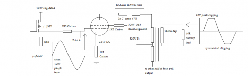
I think its best for me to include a revised schematic of my output stage so it is clear exactly what i am using.
Im very grateful for help so far.
I can see the 807 grids go to 50V peak before clipping which is easily enough to drive them fully on (data sheet quotes 86V grid to grid, this equates to 100V grid to grid!).
HT drops from 520V no signal to 425V (well into clipping). The drop in HT has no effect on the fixed bias voltage or any effect on the preceding voltage amplification stages (i checked with the scope).
Yet again im beat :/, cant see any oscillaltion which is good though, so cheers for helping me with that problem!
I think its best for me to include a revised schematic of my output stage so it is clear exactly what i am using.
Im very grateful for help so far.
Attachments
I should keep my mouth shut, since I'm the least educated person who's posted in this thread, but if you're using fixed bias and your plate to cathode is swinging ~ 100 volts, I'd expect that you may see funny things occurring as your operating point swings all over the place. Therefore, it's my uneducated WAG that you need a stiffer PSU.
The above shot in the dark aside...this is a guitar amp...how does it sound? You seem to be treating it like a hifi rig.
The above shot in the dark aside...this is a guitar amp...how does it sound? You seem to be treating it like a hifi rig.
Your right, too much analysis of a guitar amp is blasphemy!
It sounded great at the 20 odd watts it was putting out i would be happy really if i knew it was working properly but somthing is wrong if i cant even squeeze at least 40W out of a pair of 807's and im trying to figure out what.
I tried connecting screens to HT via 22K to eliminate them being starved to no avail..
I can only think of supply sag at the moment as you said. but thats a catastrophic disaster as this thing in pretty much built around a 450-0-450 @230mA mains tranny :/
Miles;
I don't quite understand why more suppressive inductance is needed in the anode path when there is already enough L provided by the output transformer.
Although there are designs around with R/L in each anode leg (as you note near top cap), I had always assumed the problem of Barkhausen is inherently the electron physics and working conditions of the tube causing oscillation near cutoff.
I've seen sim on squaring + peaks when an AB p-p amp is grossly overloaded, the problem in my instance was caused by poor tube layout, i.e minute anode capacitance interacting with an unscreened input tube.
These symptoms indicate poor layout and incorrect global nfb components but you mention 807's are notorious for this, only because of the radiating langky anode wire ? Why not screen it ?
Are the same symptoms apparent with tubes uisng IO bases ?
opinions
richj
An interesting development..
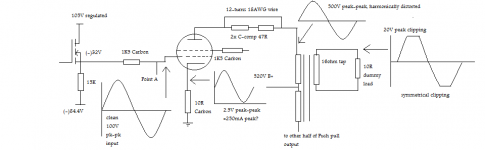
did some more investigation into the output stage and im getting about 250mA peak accross the cathode resistors of the output tubes.. this is good.. data sheet quotes 240mA peak plate current for 75W AB2! (it says values are for 2 tubes again though?? getting confused with these 2-tube quotes.)
Voltage on the primary of the transformer swings roughly 500V.. cant be bad..
Is this functiong correctly then?
is my seemingly puny swing into 10 ohms due to a load mismatch from pri to sec? maybe ill try the 8 ohm tap into a 10 ohm load and see if i can get the power into the resistor that way.
Attached a new schematic to show what im drivelling about.
Attachments
Hi Shifty,
Its a 5R4 tube rectifier followed by 10uF => 17H => 500uF.
Voltage sags 52V across rectifier , the rest is across the choke. I checked the transformer loading and it drops in output by ony 3VRMS (phew).
been squeezing this amp for power just now and got it to do
43.4WRMS into 8.4R
35WRMS into 3.2R
--with 7Khz sine wave
Far from the 75W i was hoping for... it just seems to clip softly then the jagged harmonics creep in of the waves whenever i push it harder.
just dont know whats going on really?? unless its oscillating beyond the bandwidth of my scope.. (2Mhz Tek )
)
I can only really imagine that the output transformer is not the correct match for the tubes, its 5KCT according to Hammond ( model 1650R) this should be pretty well matched for the 4k6 value for 807's in data sheet though..
Its a 5R4 tube rectifier followed by 10uF => 17H => 500uF.
Voltage sags 52V across rectifier , the rest is across the choke. I checked the transformer loading and it drops in output by ony 3VRMS (phew).
been squeezing this amp for power just now and got it to do
43.4WRMS into 8.4R
35WRMS into 3.2R
--with 7Khz sine wave
Far from the 75W i was hoping for... it just seems to clip softly then the jagged harmonics creep in of the waves whenever i push it harder.
just dont know whats going on really?? unless its oscillating beyond the bandwidth of my scope.. (2Mhz Tek
)I can only really imagine that the output transformer is not the correct match for the tubes, its 5KCT according to Hammond ( model 1650R) this should be pretty well matched for the 4k6 value for 807's in data sheet though..
richwalters said:Miles;
I don't quite understand why more suppressive inductance is needed in the anode path when there is already enough L provided by the output transformer.
It's quite common in RF designs; not so much for audio. In either case, the idea is the same: break up the resonant circuit formed by OPT leakage inductance, VT plate capacitance, OPT and circuit stray capacitance. The parallel 100R resistor de-Qes the coil so that it doesn't ring at its natural frequency. It only works if connected right at the plate terminal.
I had always assumed the problem of Barkhausen is inherently the electron physics and working conditions of the tube causing oscillation near cutoff.
I've seen sim on squaring + peaks when an AB p-p amp is grossly overloaded, the problem in my instance was caused by poor tube layout, i.e minute anode capacitance interacting with an unscreened input tube.
Barkhausen Effect creates a negative resistance characteristic. That may, or may not, lead to oscillation, depending on whether or not the stray circuit satisfies the Nyquist Criterion for oscillation. Loading down that stray circuit kills any oscillation. This is what plate and screen stoppers are for.
These symptoms indicate poor layout and incorrect global nfb components but you mention 807's are notorious for this, only because of the radiating langky anode wire ? Why not screen it ?
An ill-concieved layout will definitely contribute to instability, as will the gNFB loop. However, the "snivets" problem that you get with 807s didn't occur with 6BQ6GTBs, even though this is also a type where the plate connection is made at a button on top of the VT, leading to longer leads between the plate and the primary of the OPT. The 6BQ6GTB PP final didn't show any damped oscillations at the transitions (just the normal switching glitches) even with no plate or screen stopppers. I added them anyway, just to make sure, before connecting the gNFB.
As for shielding the plate lead, that might make things worse, due to shield-to-inner conductor capacitance.
Are the same symptoms apparent with tubes uisng IO bases ?
I doubt that has anything to do with it. Some types have a greater tendency to produce those types of oscillation than others. Ideally, what they should have done is equip the 807 with a seven pin base, and made a separate connection to the beam formers so that you could bias them positive, as was done with the 813 and 802, and is done with some of the HD power finals.
- Status
- This old topic is closed. If you want to reopen this topic, contact a moderator using the "Report Post" button.
- Home
- Amplifiers
- Tubes / Valves
- 807 AB2 oscillation maybe?