kevinkr said:Hi Sheldon,
I think in terms of a horn running above 300Hz that there should be no audible hum at all at any distance.. (Ouch!)
A bigger concern is all of that spectra extending from near dc to light, when you do a root square summation that is one heck of a lot of noise even though individually they are pretty far down.
I think it would be better to use constant current dc to heat the filaments and use some additional chokes in the filament lines for improved high frequency isolation from the supply if that concerns you. (I no longer use the chokes as it doesn't seem necessary in my electrical environment.) Linear Tech makes some wonderful ldo's that are perfect for use as constant current regulators. Take a look at the LT1083, LT1084, and LT1085 series. You would need one for each DHT with a separate filament winding, bridge rectifier and a couple of electrolytic caps, plus a couple of resistors - very simple. Current can be made adjustable if needed..
It should be possible to reduce the noise down to less than 0.5mVrms broadband with a very simple regulator, good layout and some shielding if necessary. This should result in virtually no audible noise at the speaker.
Some other thoughts about the filament supplies. All of that hum cancelling circuitry is more complicated than a simple dc filament supply for the 801's.. AC heating without any finagles should be fine for the 6SN7, just tightly twist the filament wires, make sure that there are no "loops" around the socket and if there is a center tap either ground it or elevate it maybe +20V above ground with a resistive divider, and bypass same with a moderately sized el. cap.. 1mA ought to be enough current in the divider so you might try 20K and a 280K resistor in series, with bypassing by 22uF/35V cap to ground. Should there be no center tap a pair of 100 ohm resistors in series across the filament transformer will accomplish the same goal as a connection point for the divider or ground connection.
Kevin
Edit: Added some other thoughts..
Thanks Kevin. Ouch is right! I guess I was starting to lean along those lines. It was fun doing the cancellation, but I don't have Steve Bench's skills or equipment. I was thinking of Guido Tent's constant current filament supplies. But I may also want to keep it more DIY, so your suggestions are very helpful and also pretty much pushed me over the edge. I'm going to build another one of these and can order the power transformer with separate windings for each output tube. Meantime, can i run both supplies from one filament supply but with two bridges, with the intent to replace when I order transformers for the second amp? I'll probably elevate the 6SN7 filament too, just because it's easy. I'll post some pics when I'm "finished".
Sheldon
Hi Sheldon,
Sounds like a good plan, and since this design uses fixed bias the existing unit can be converted for dc filament operation, however in this case you would need to use constant voltage, not current operation because of the shared secondary, however you can use a single regulator, schottky bridge, caps and a couple of resistors (set voltage) to power both tubes. Alternately you can use a pair of regulators set up to source 7.5V and reconfigure them later for constant current operation. I recommend you design them yourself, referring as need to the LT tech notes and feel free to run things by me if you feel you need a second opinion. Trying new things is the way to go..
Transformers could be one of several brands of toroids available from digikey or mouser. (They're inexpensive and quickly available.) Suitable ratings would be 10V @ 2A per winding to allow for low line and some losses in the rectifiers and elsewhere. Arguably the lack of electrostatic shielding in most toroids could be an issue, but this is what I did and I have not yet had any reason for regret..
Thanks Kevin for the suggestions. You may live to regret this one though.
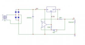
(deep breath), Ok how about something like this? Yes, undoubtedly more complicated than necessary. But I was thinking of an easy way to adjust voltage (FWIW I'm using Steve's "starved filament" for this, at about 6.7V). And, using a 1ohm resistor or so burns up 1V of the supply capability. I'd like to see if I can use the one filament winding I have and add one extra filament transformer. Anyhoo, hammer away:
kevinkr said:
I recommend you design them yourself, referring as need to the LT tech notes and feel free to run things by me if you feel you need a second opinion.
(deep breath), Ok how about something like this? Yes, undoubtedly more complicated than necessary. But I was thinking of an easy way to adjust voltage (FWIW I'm using Steve's "starved filament" for this, at about 6.7V). And, using a 1ohm resistor or so burns up 1V of the supply capability. I'd like to see if I can use the one filament winding I have and add one extra filament transformer. Anyhoo, hammer away:
Attachments
Hi Sheldon,
Interesting circuit with some probable risk of instability, I would recommend simulating it in LTspice prior to building it. (If you don't have it download it from LT website now! LOL Umm, it will also do tubes.) The op-amp would need to have rail to rail inputs and outputs as most conventional types don't have sufficient common mode range to operate so close to the supply rail, and the output is operating not far removed from the raw supply particularly under low line conditions. You probably want to add some dominant pole compensation in the feedback loop of that op-amp.
This is not an issue if you temporarily operate the regulators in the voltage domain as the reference voltage does not influence the regulator drop out voltage - with the current transformer that's what I would recommend temporarily, and because it is shared between two filaments I would ground the negative side directly to reduce the potential for cross-talk between the two channels.
In the final version you can raise the raw supply sufficiently to assure adequate drop out margin under low line conditions.
Kevin
Hi Sheldon,
One other quick thought, while I understand that starved filament operation may improve linearity significantly it will also substantially reduce tube life in many cases, particularly in dht power tubes. The reduced filament temperature may result in a process analogous in some ways to cathode stripping.
Kevin
kevinkr said:Hi Sheldon,
One other quick thought, while I understand that starved filament operation may improve linearity significantly it will also substantially reduce tube life in many cases, particularly in dht power tubes. The reduced filament temperature may result in a process analogous in some ways to cathode stripping.
Kevin
Ok, whew, I'm going to have to chew on that first reply some before I can comprehend it all. As regards the filament voltage, that's one reason I wanted an easy way to adjust voltage, but with constant current (seems like a good idea). Anyway, buried on Steve's site is this analysis:
http://members.aol.com/sbench/heater.html
At the bottom of the page he postulates that the starved filament should be ok as long as the current is reduced appropriately. Sounds reasonable?
Sheldon
@ Kevinkr
I suppose you are using DC heaters giving 7.5V out and dropping the extra 1.25V with a 1R... Did you tried a starved filament with a current source heater?
Did you noticed any difference in the sound ... (improvement I hope) starving the tube?
Just asking, as I am (well I was actually) using a current regulated supply for my 801A but I fed the tube with the nominal 1.25A and I was planning to starve it at 1.1A or so for the next amp.
Ciao
Gianluca
kevinkr said:Hi Sheldon,
I would recommend simulating it in LTspice prior to building it. (If you don't have it download it from LT website now! LOL Umm, it will also do tubes.)
Kevin
So you mean LTSpice/SWCADIII? I don't see any other LTSpice. I downloaded it, but have no clue as to how to use it to make a circuit and simulate it. Closest I've come to that is using PSUD, which has far far fewer choices. I've used Tiny CAD but only to make the schematic drawings. I'm willing to give it a shot, but I'm not sure I have the time it seems it might take to become even passably proficient with it. I can't even find a transformer on this one.
Sheldon
Hi Sheldon,
For the purposes of simulating the regulator circuit you propose you can use a simple voltage source which is in the main library.
Ltspice/SWcadIII is an extremely powerful tool and easy to use once you have spent a few hours with it. It will answer a lot of questions.
Kevin
For the purposes of simulating the regulator circuit you propose you can use a simple voltage source which is in the main library.
Ltspice/SWcadIII is an extremely powerful tool and easy to use once you have spent a few hours with it. It will answer a lot of questions.
Kevin
kevinkr said:Hi Sheldon,
You probably want to add some dominant pole compensation in the feedback loop of that op-amp.
This is not an issue if you temporarily operate the regulators in the voltage domain as the reference voltage does not influence the regulator drop out voltage - with the current transformer that's what I would recommend temporarily, and because it is shared between two filaments I would ground the negative side directly to reduce the potential for cross-talk between the two channels.
In the final version you can raise the raw supply sufficiently to assure adequate drop out margin under low line conditions.
Kevin
I'm not sure exactly what you mean here. May take me a while to be sure. I probably won't run on a common supply, but will get and additional supply to go with the one in the power transformer. That one is 7.2 volts and I'd like to run at about 6.6VDC.
Would this help with stability issues?
Attachments
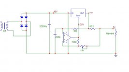
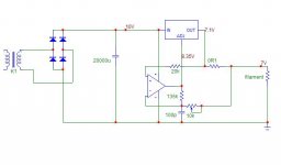
Or better something like this?
BTW, I'm assuming here that we want the roll off above the audio range. If I make it below the range, it would become a voltage source at audio frequencies no?
I know these aren't complete, but since I didn't get laughed off the forum with the first one, I'm plugging away.
Still working at LTSpice, but I think it'll take a while. Meantime I just want to know if this is reasonable as a general direction.
Attachments
Not here & now ... but it was quite simple
bridge
10000uF
2mH
10000uF
LM317 (heatsinked) to regulate 10V
LM317 (heatsinked) to set 1.25A
you can drop the first LM317 ... I use it to drop the extra volts I get from the bridge ... well it's flattening somehow the supply btw.
Ciao
Gianluca
bridge
10000uF
2mH
10000uF
LM317 (heatsinked) to regulate 10V
LM317 (heatsinked) to set 1.25A
you can drop the first LM317 ... I use it to drop the extra volts I get from the bridge ... well it's flattening somehow the supply btw.
Ciao
Gianluca
CCS filament regs.
Hi there,
When I built my Shishido 801A amp, I used CCS regs. (LT1085) for the 801A filaments. Unfortunately, I found that because the filaments are designed to be run at constant voltage, the current draw for 7.5V varies quite abit from tube to tube. Thus, running at constant current made them glow at different brighness. This isn't too good for the tubes (or sound, probably), so I added a variable resistor to the series resistance to allow me to trim the voltage across the filament to 7.5V.
Cheers,
Pete
I used the 801A as driver for a pair of 2A3s. For your info it was a parafeed stage. If I were in your boots, I'd build a parafeed amp too ...
I hope to post the heater schem as I will be back at home (at work now).
I did notice the same effect as reported by i_sould_coco ... I adjusted that sensing resistor in the LM1084 (I used that too ... not the LM317) to get something close to 7.5V: sometime you will need to pick up the most suitable resistor among a bunch of 1R's as they can differ +/-5% due to their tollerance. Tollerance really matters here but you don't need to use "0.1% resistors" ... just choose the most suitable "5% tollerance resistor".
In case you go for it, keep in mind that when you light the tube you will find that the heater's voltage is quite low (lets say 6.5V or less) even if it is sinking 1.25A: it takes 5-10 mins to reach a steady value increasing slowly.
I believe tubes do like to be heated this way.
Would be intersting to investigate, as I was writing, if lowering the heating power (that is current or voltage as S. Bench did) is beficial to distorsion/sound. I can't do that now as I dismantled that amp but, coco, if your amp is still running ... well just let us know.
Ciao
Gianluca
Hello, yeah, this is my current day to day amp. I actually went to the trouble of providing metering/adjustment externally because I found the tubes would vary so much and didn't want to dismantle the amp every time! So I can try this very easily.
Normally just run then at just a whisker under 7.5V, but I will try lowering the voltage to see if it makes any difference to sound. I'll let you know if I hear any differences at lower voltage.
Cheers,
Pete
Normally just run then at just a whisker under 7.5V, but I will try lowering the voltage to see if it makes any difference to sound. I'll let you know if I hear any differences at lower voltage.
Cheers,
Pete
i_should_coco said:
Normally just run then at just a whisker under 7.5V, but I will try lowering the voltage to see if it makes any difference to sound. I'll let you know if I hear any differences at lower voltage.
Cheers,
Pete
If you like it and want to run that way long term, be sure to check out the reference I cited above on current vs. heater voltage. The 801 is rated for 85ma cathode current normally. According to Bench, if the voltage is lowered to around 6.5 or so, the max current should then be reduced to 70mA or less. Actually, reading the article, what you'd really want to know it the filament wattage. The current limit should be proportional to that.
Sheldon
- Status
- This old topic is closed. If you want to reopen this topic, contact a moderator using the "Report Post" button.
- Home
- Amplifiers
- Tubes / Valves
- 801 low power SE amp