I'm a budding DIY audiophile who recently bought a tiny two-seater convertible (BMW Z3) project car. The largest space to install a subwoofer in the cabin is on the floor in front of the seats with the thighs resting on top of it. The space available is about 9" tall, 9" deep, and 18" wide- which is about 0.84 cubic feet.
I'm picturing building a "bass tube" style design similar to this to put right in front of the seats:

I would just buy one of these except for:
1. The enclosure is slightly too tall to fit
2. From what I understand, I could possibly achieve a smaller enclosure by utilizing a passive radiator design.
So now I'm trying to figure out how to design the ultimate daily driver subwoofer to fit with in this small space. I'm picturing an enclosure similar to the one pictured above with an 8" subwoofer on one end, and a passive radiator on the opposite end of the tube.
I'd like to squeeze a lot of power out of this thing so I'm looking at something like the Dayton Audio Ultimax 8" subwoofer and pairing it with something like the Earthquake Sound SLAPS-M8 passive radiator. I understand the passive radiators should displace 1.5-2x the volume of the powered driver and the SLAPS-M8 has 3.5in (88mm) Xmax so I figured that should be plenty.
However: I can't quite figure out the math to see if these would work together.
Dayton Audio recommends this ported enclosure:
Volume: 0.75 cubic ft. (net internal, not including driver or port volume)
Tuned to: 30 Hz
Port: 10" wide by 1" high slot port that is 30" long, which yields an f3 of 30 Hz.
I read that the passive radiators MMS rating should roughly match the weight of the of air within the port volume. If my calculations are correct, the port volume is 300 cubic inches and the weight of that air is about 6 grams.
However, the SLAPS-M8 passive radiator MSS is 75.6g, which seems way off by an order of magnitude. This is surprising to me and I don't really understand where to go from here.
Hoping some of you veteran passive radiator guys can give me some direction, clarification, correction - or maybe just a reality check on this project.
Thanks, guys!
PS: I'm not using any software right now (just home brewed spreadsheets) and am open to any recommendations for software that could aid with this type of design.
I'm picturing building a "bass tube" style design similar to this to put right in front of the seats:
I would just buy one of these except for:
1. The enclosure is slightly too tall to fit
2. From what I understand, I could possibly achieve a smaller enclosure by utilizing a passive radiator design.
So now I'm trying to figure out how to design the ultimate daily driver subwoofer to fit with in this small space. I'm picturing an enclosure similar to the one pictured above with an 8" subwoofer on one end, and a passive radiator on the opposite end of the tube.
I'd like to squeeze a lot of power out of this thing so I'm looking at something like the Dayton Audio Ultimax 8" subwoofer and pairing it with something like the Earthquake Sound SLAPS-M8 passive radiator. I understand the passive radiators should displace 1.5-2x the volume of the powered driver and the SLAPS-M8 has 3.5in (88mm) Xmax so I figured that should be plenty.
However: I can't quite figure out the math to see if these would work together.
Dayton Audio recommends this ported enclosure:
Volume: 0.75 cubic ft. (net internal, not including driver or port volume)
Tuned to: 30 Hz
Port: 10" wide by 1" high slot port that is 30" long, which yields an f3 of 30 Hz.
I read that the passive radiators MMS rating should roughly match the weight of the of air within the port volume. If my calculations are correct, the port volume is 300 cubic inches and the weight of that air is about 6 grams.
However, the SLAPS-M8 passive radiator MSS is 75.6g, which seems way off by an order of magnitude. This is surprising to me and I don't really understand where to go from here.
Hoping some of you veteran passive radiator guys can give me some direction, clarification, correction - or maybe just a reality check on this project.
Thanks, guys!
PS: I'm not using any software right now (just home brewed spreadsheets) and am open to any recommendations for software that could aid with this type of design.
Last edited:
Thanks, GM!
Update:
Any thoughts on my driver/radiator selection and what I might be missing?
Update:
- I got WinISD (for the first time)
- I added several Dayton Audio drivers to the database (Ultimax 8", and RSS210HO-4 8").
- I made a new passive radiator project
- I tried adding the parameters from several passive radiators (Earthquake SLAPS-M8 and Dayton Audio RSS265-PR 10") and clicked "Next"
- WinISD goes to the "Choose Alignment" page showing an empty dropdown that says "<None Available> with a message saying Current version of WinISD can't calculate alignments for chosen box type
Any thoughts on my driver/radiator selection and what I might be missing?
Hmm, haven't used WinISD since 2015 according to this and don't recall if the old 'pro' version had the option, though apparently it did, so do a web search as there's several tutorials around, just not necessarily for the current version, so may need to play with it a bit till it works.
That said, your 'passive radiators should displace 1.5-2x the volume (Vd) of the powered driver' is a bit misleading in that it's the driver's effective piston area (Sd) since this ROT was derived back when woofers had just a few mm of Xmax and not much more Xlim, so normally just used 1.5-2x frame size to ensure having plenty of effective piston area, ergo wondering if the PR's you're simming meets this.
edit: not saying using (Vd) won't work once figured out, just that it seems reasonable that any old program will be designed for the old ROT.
Last edited:
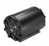
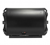
I just came across the Kicker TB8 (photos attached) which is basically what I'm looking to build. It's a compact bass tube with an 8" driver on one end and an 8" passive radiator on the other end that happens to fit within the allotted space in the car.
I'd like to design and build a DIY version like this Kicker design but using better components for better power handling. I'm just having trouble finding the right driver and passive radiator for the project.

I'd like to design and build a DIY version like this Kicker design but using better components for better power handling. I'm just having trouble finding the right driver and passive radiator for the project.
Attachments
- I got WinISD (for the first time)
- I added several Dayton Audio drivers to the database (Ultimax 8", and RSS210HO-4 8").
- I made a new passive radiator project
- I tried adding the parameters from several passive radiators (Earthquake SLAPS-M8 and Dayton Audio RSS265-PR 10") and clicked "Next"
- WinISD goes to the "Choose Alignment" page showing an empty dropdown that says "<None Available> with a message saying Current version of WinISD can't calculate alignments for chosen box type
Any thoughts on my driver/radiator selection and what I might be missing?
You're not missing anything as such, it's just that you have to do a bit of work yourself rather than the program being able to do it all for you.
Just click "next" to move on to the next stage (IIRC, assigning a name to the project), then "create" and you'll get into the main part of the program.
From there, it's up to you to adjust the box size, & tuning frequency (by adjusting the added mass of the PR) to see if you can optimise the frequency response, while making sure you don't exceed Xmax at the SPL levels you're likely to operate at.
https://www.earthquakesound.dk/wp-content/SLAPS/index.htmlAny thoughts on my driver/radiator selection and what I might be missing?
According to their calculator, the SLAPS-M8 is so heavy the Fb in a 21 Liter (.75 cubic foot) box is 21 Hz, dropping the box to a tiny 12L raises the Fb to 28Hz.
The SLAPS-M8 specs you linked say it has a "preinstalled 160g mass", removing some (or most..) of that mass should bring the Fb up to 30Hz in a .75 cubic foot net enclosure.
The specs also claim the SLAPS-M8 has a 3.5" Xmax, which would be 7" peak to peak, not possible with that surround.
Even 3.5" peak to peak, an Xmax of 44.5mm, seems high for an 8" PR.
Looking at the rear of the SLAPS-M8, it seems likely that 3.5" is a misprint for 35mm peak to peak excursion.
That would be around the same displacement as the Dayton UM8-22's 16mm Xmax, the SLAPS-M8 might run out of excursion before the UM8-22 does.
Last edited:
I have a small sub I'm still building on. I uses a TB W8-740P and a SLAPB M8 Without added weight ... so not like the picture above ... no screw going through ...
The drivers are mounted in a 10,7 liter box.
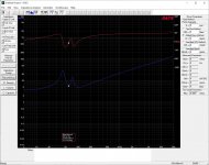
I just made an impedance measurement to verify mu assumed parameters used in WINisd. It matches quite well giving a resonance around 58 Hz. See picture.
In WINisd I'm using the following parameters for the M8:
VAS = 32 l
Fs = 30 Hz
Qms = 7
Sd = 189 cm2
Xmax = 20 mm
Totally agree the 3.5" Xmax,pp is not possible ... that is why I have set it to 22 mm
I also have a Earthquake Tremor X 10-4 and SLAPS M10 .... it seems like a much better combo, so if you can find room for that this is highly recommended. ....on the other hand nothing bad to say about the M8, but it will not get you much below 30 Hz
The drivers are mounted in a 10,7 liter box.
I just made an impedance measurement to verify mu assumed parameters used in WINisd. It matches quite well giving a resonance around 58 Hz. See picture.
In WINisd I'm using the following parameters for the M8:
VAS = 32 l
Fs = 30 Hz
Qms = 7
Sd = 189 cm2
Xmax = 20 mm
Totally agree the 3.5" Xmax,pp is not possible ... that is why I have set it to 22 mm
I also have a Earthquake Tremor X 10-4 and SLAPS M10 .... it seems like a much better combo, so if you can find room for that this is highly recommended. ....on the other hand nothing bad to say about the M8, but it will not get you much below 30 Hz
Attachments
Baldin, thanks for the info! That looks good. In my case, i've been trying to tune a sub 1.0cuft to around 30hz so enclosure so my goal has been a bit different.
My bad results:
After experimenting in WinISD with a variety of drivers and passive radiators, it seems my naive hopes/expectations for passive radiators was overzealous. I have been unable to find any combination of 8in drivers and 8in passive radiators within a sub 1.0cuft space that will provide the response curve I'm looking for (relatively flat, smooth response, still strong at 30hz, rolling off smoothly below 30hz). Every combination of drivers and PRs I've tried (even PRs with huge xmax ratings) would not provide a response curve I'd be willing to invest in. The best I was able to create peaked around 50hz and rolled off fairly quickly with 30hz coming in around -10db. My guess is that Kicker TB-8 has a similar response curve.
My good results:
Once I stepped up to 10-in passive radiators, the curve started to look very reasonable - even in tiny enclosures (0.7cuft, etc). Pretty amazing! Most 8in subs including the Dayton Ultimax and Reference series play extremely well with the Earthquake SLAPS-10 in a small enclosure once you start adding some weight to it (150-250 grams).
In my particular vehicle 10in PR does not fit on the floor in front of the seat - so I'm going to scrap the concept behind this thread. However, if anyone's interested in a <1cuft box and you can fit a 10" passive radiator in there, there do seem to be options worth exploring.
My new approach: Custom fiberglass that fits behind both seats with a 10" forward-facing sub between the seats and two 10" passive radiators, one behind each seat. It shouldn't cost me much more, it will be even deeper and louder than the 8" design - but will be a LOT more labor to fabricate. I've never done fiberglass before so wish me luck!
Best,
Jeff
Im sure you have done a search for enclosures for the Z3
There is already made custom sub enclosures for around 200 dollars.
After time labor ,material and resin, plus the learning curve
200 might not be so bad.
On the flip side, Youtube is full of Fiberglass videos for car subs
and is rather fascinating process.
So as far as diy adventure.
It could be rather fun.
One thing that might help is isobaric loading which you can model in
WinIsd.
The main thing working against you is enclosure volume which you would need
for deep bass.
Isobaric would make 2 drivers behave as if they were in twice the space.
1 cubic foot can have a 2 cubic foot response.
So a pair of 10inch would do rather well.
Here is 2 designs using the Dayton UM88-22 in Isobarik configuration.
Orange Line =
1 Cubic Feet, ported, Fb 25 Hz, F3 response 21 Hz
Yellow Line =
1 Cubic Feet, Passive Radiator, Fb 28 Hz, F3 response 25 Hz
Passive Radiator = SLAPS-M10 with 140 Grams of mass added

When you select your project in WinIsd
use the Iso-barik (compound) option

Orange Line =
1 Cubic Feet, ported, Fb 25 Hz, F3 response 21 Hz
Yellow Line =
1 Cubic Feet, Passive Radiator, Fb 28 Hz, F3 response 25 Hz
Passive Radiator = SLAPS-M10 with 140 Grams of mass added
When you select your project in WinIsd
use the Iso-barik (compound) option
Last edited:
The intention is of course to add mass so the resonance freq gets down to a 30 Hz, and then eq it by DSP ... just not come around to doing it yetBaldin, thanks for the info! That looks good. In my case, i've been trying to tune a sub 1.0cuft to around 30hz so enclosure so my goal has been a bit different.
") ....... too many open projects.
....... too many open projects.The post was to give and verify the T7S parameters for the SMAPS M8, so it can be sim'ed properly
If as you say, you can fit a 10", it all becomes much more interesting.
not sure if the the tiny cabin of the beemer can be considered as "free air", given the tightness of german cars.
That is why I see in competiton car audio only sealed cabinets.
Unless you want to impress the audience outside the car, and leave the top off.
That is why I see in competiton car audio only sealed cabinets.
Unless you want to impress the audience outside the car, and leave the top off.
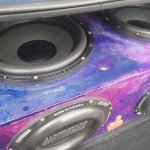
Did this turn out well? Just did another PR Box and it sounds awesome. Used 4 SlapsM12s...
jassky's Post #11 on 2022-08-06 was his last post here..
Did the tuning on your SLAPS M12s come in as their charts predict?
I didn't use the weights. It was too low. I like to hear my music and feel it. Read somewhere without mass it was 30hz. They would definitely do better
 in home theater or a smaller box in car audio. I also took out the Prides (Qts .66) and replaced with Earthquake DBXi 15s. It was good with the Prides but much better with the EQs.
Attachments
- Home
- Loudspeakers
- Subwoofers
- 8-inch "bass tube" w/ passive radiator (Enclosure Design)