Re:"Many vintage designs use the same small signal circuitry with 7591s and "12" W. types. That definitely will not work with 6L6 family types."
I agree with you the 6L6 family will not simply drop into a 7591 drive circuit design. It is however possible to modify the drive circuits in a 7591 design to accommodate a 6L6 family member. While the changes needed are not few and not always simple the basic topology of a 7591 drive circuit can with the required changes serve quite well driving a 6L6 family member. Comparing the Dynaco ST-70/Mark3 drive circuits that provide the larger required gain and drive signal levels for 6550/EL34 (similar to 6L6 drive requirements) it can be seen the drive circuits are not all that different from what one finds in a Scott or Heath 7591 design. The detail are different yes and important but the topology is much the same. This suggested to me that most 7591 amplifiers could have their drive circuits modified to provide the required drive for a 6L6 family tube. When I considered not being able to source 7591 tubes into the future was a death sentence to many a wonderful old unit I though modification was preferred to the unfortunate fate of many 7591 based units being taken apart for scrap value.
What I found was the following.
Bias must change from about -21V to -41V for fixed bias.
Grid bias feed resistors of the 7591 changes from 330K~470K to 100K for bias stability.
Drive stage to grid coupling caps increase in value by the same ratio the grid bias feed resistors decreased by to keep the driver LF knee constant. The phase splitter plate/cathode resistors need to be set to about 33K to provide the required drive current for the reduced grid resistors.
More drive stage gain is needed and this can be had by changes in the pentode circuit just before the phase splitter. This is bit complex but doable. Many 7591 designs use a 1K resistor in the pentode cathode and this degenerates the pentode gain significantly. Looking to the ST-70 pentode drive circuit provides hints as to what could work for more gain.
Once I learn how this forum works I will attach the drive circuit I used with a AA-100 using the 6p3s-e. It provides the comparable gain, damping factor, distortion and power levels to the original 7591 design and proven very reliable.
The key draw back I found of many replacements for the 7591 is replacements are taller and will not fit in the available space inside the amplifier.
really narrowed the field of possible replacements.
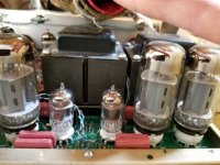
This was a key reason I looked at the 6n3p-E, it fit in the case!
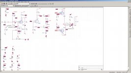
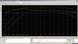
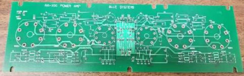
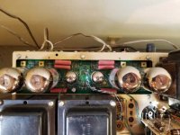
Here is my drive circuit for the 6n3p-E adapted from what was inside the AA-100. This version provides the same power as the 7591 version with THD about the same. Damping factor is much improved over the AA-100 circuit and so is low frequency stability. This circuit is quite stable even with no speaker load attached. Yes it is a lot of drive circuit changes and not applicable to all 7591 amplifiers drive circuits (12AX7 based versions are a different problem) but perhaps better than the option of parting out vintage 7591 amplifiers. I eventually I created a PCB board to replace the AA-100 power board to make the changes easier and to replace burnt AA-100 circuit boards.
really narrowed the field of possible replacements.
This was a key reason I looked at the 6n3p-E, it fit in the case!
Here is my drive circuit for the 6n3p-E adapted from what was inside the AA-100. This version provides the same power as the 7591 version with THD about the same. Damping factor is much improved over the AA-100 circuit and so is low frequency stability. This circuit is quite stable even with no speaker load attached. Yes it is a lot of drive circuit changes and not applicable to all 7591 amplifiers drive circuits (12AX7 based versions are a different problem) but perhaps better than the option of parting out vintage 7591 amplifiers. I eventually I created a PCB board to replace the AA-100 power board to make the changes easier and to replace burnt AA-100 circuit boards.
Attachments
EL34s use 4 Kohm primary PP O/P "iron" and that's bad here. Both 7591s and 6L6s use 6.6 Kohm stuff. So, solve the small signal drive issue and the Russian 5881s will be OK.
Fisher equipment uses a 12AX7 section voltage amplifier and a 12AX7 section "concertina" phase splitter that's already problematic in combination with current production 7591s. Fisher took liberties with the documented grid to ground resistance limit and current production 7591s "dislike" that. Bottom line, NO Russian 5881s in a unit Fisher manufactured.
Scott 299s/LK72s outfitted with either a 6GH8 or 6U8 might be candidates for the Russian 5881 swap. Depending on version, Scott schematics sometimes show a 6BL8 but the pentode in that type exhibits somewhat lower gm (gain) than that in a 6U8. This substitution idea requires all the gain that can possibly mustered up from the small signal circuitry.
- Status
- This old topic is closed. If you want to reopen this topic, contact a moderator using the "Report Post" button.