Member
Joined 2009
Paid Member
")
In the UK feedback in radio sets was not common. I suspect that the rest of Europe was the same. I still suspect that the US was the same.Keit said:Feedback was very common.
No scrambling at my end. Second-order nonlinearity (with no feedback) gives rise to second harmonic and second-order IM products. Add feedback and all orders appear - both harmonics and IM - I just listed the third-order ones. You appeared to be disputing this.Keit said:No. your terminology was scrambled. Taking your example listing of products which can arise in a device having a square law transfer response and feedback, all in your list are 3rd order, which I'm sure you know, so I can't see what you are getting at.
I did not say that the IM order is the order of the transfer characteristic. I know it is not. Second-order nonlinearity (i.e. square law) gives second-order IM (i.e. f1+f2, f1-f2) - this is what I said. Third-order nonlinearity gives third order IM. Fourth-order nonlinearity gives both second-order and fourth-order IM etc.You terminlogy in your earlier post was scrambled because you said that the IM order is the order of the device transfer. A different thing.
The first link is someone's web concoction - not a genuine circuit. Australian production was much the same as "All American Five" until the availability of television triode pentodes. Typical line up before TV tubes became available was 6BE6+6BA6+6AV6+6AQ5 with 6X4 rectifier. In five-tube sets the 6AQ5 was near universal. Some brands used a 6AN7 convertor instead of the 6BE6. Four tube radios were often reflexed and used 6AN7+6BA6+6BV7 with 6X4 but there were other combinations.
Virtually all battery sets were 1T4+1R5+1T4+1S5+3V4. As there is quite enough gain with the RF stage before the converter, there was always negative feedback. As hum is non problem in battery sets, it took the form of a high value resistor between the plate of the 1S5 and the plate of the 3V4. Sets with only 1R5+1T4+1S5+3V4 were made but only in small numbers. As there is barely enough gain without the RF stage to pick up all local stations (2kW output was usual) in most suburbs, there was no neg feedback in 4-tube sets.
Four tube sets were far more common in Britain, as those law-abiding rule-following radio licence-paying British just listened to one of the high power (50 kW) BBC stations. Or maybe Radio Luxemburg or the Radio Caroline pirate if Dad wasn't around. And there was a tax on each tube socket for quite a while. So you saw sets with only 3 tubes - the rectifier was a selenium rectifier. Not durable, even compared to a tube rectifier, but it avoided some socket tax.
Last edited:
Were they? A typical UK AM set had frequency changer (ECH81), IF amp (EF85 or 89), detector+triode (EBC90), audio output (maybe EL84) and rectifier (EZ80) (or their 8-pin predecessors). I make that 5.Keit said:Four tube sets were far more common in Britain,
There were some four valve sets, which typically missed out the triode audio amp and used a high gain output valve, but most were 5.
Negative feedback is just ill, very little/next to none is best haha
Blanket statements like these - everybody can make such (and often do). Care to qualify for a change, or at least give a reliable reference?
Otherwise I can state: "NFB is the best single measure to decrease an amplifier's distortion below audible level." Full stop.
And what an informative debate we have thus created .....
NFB is necessary for transistors since they aren't very linear. Tube amps designed right can get away with little or no feedback and still sound great. With no NFB, the amp presents an output impedance (.5 to 8 ohms in a tube amp I built) that scrambles the calibration of a passive crossover , and it lets the typical woofer resonance have it's way. So some NFB seems very wise.
Some circuits have huge amounts of feedback in order to brag about their distortion with a 1kHZ sinewave being .01% or better, but without a good understanding of phase margin and slewing related distortion mechanisms. This very high NFB can cause other various problems. The circuit could spuriously oscillate, or a driver transistor could try to force the slower output stage to do something it can't do, and in the process generate slewing related distortions, and possibly burn itself out (happened all the time in the 1970's). When the amp blew, it often blew the cr*p out of the speaker too. Bottom line: use NFB, but not more than you need, and learn about phase margin. Using 0.1uF power supply bypass caps right in the amp circuit becomes particularly important when NFB is high, or phase margin is next to impossible to predict.
Bob Carver admitted in an interview in Audio magazine (maybe 20 years ago), that his Phase Linear amps used to blow up for no apparent reason. He eventually figured out the concept of phase margin, and learned how to do large amounts of NFB while maintaining a good phase margin. I appreciated his honesty. He was not at all the only one who back then didn't have a good grasp of phase margin with NFB.
The 'multiplication' of harmonic distortion as discussed in the learned posts above is valid, but the practical implication is also a factor of the initial magnitudes of the components. Much of the NFB controversy arises while only taking a qualitative view. It is informative to look at practical figures to avoid a misconception.
If the circuit is 'clean' enough to begin with, harmonic regeneration does not become a concern until quite a degree of NFB is applied. The attached graphs are typical of the behaviour of what will happen to a kosher circuit as the amount of NFB is increased. It will be clear that in this instance that harmonic products starts 'coming back' only after exceeding 25 dB of NFB. (The graphs are for a transistor amplifier but the same principle applies to any amplifier. I also apologise for presenting a hand pasted-up version which I have on the pc.)
If the circuit is 'clean' enough to begin with, harmonic regeneration does not become a concern until quite a degree of NFB is applied. The attached graphs are typical of the behaviour of what will happen to a kosher circuit as the amount of NFB is increased. It will be clear that in this instance that harmonic products starts 'coming back' only after exceeding 25 dB of NFB. (The graphs are for a transistor amplifier but the same principle applies to any amplifier. I also apologise for presenting a hand pasted-up version which I have on the pc.)
Attachments
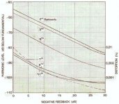
The attached graphs are typical of the behaviour of what will happen to a kosher circuit as the amount of NFB is increased. It will be clear that in this instance that harmonic products starts 'coming back' only after exceeding 25 dB of NFB.
Interesting graph. Where did it come from?
I have in fact seen similar graphs elsewhere - always for solid state amps, never for tube amps.
It provides an alternative explanation of why only a few dB of neg feedback makes typical "All American Five" tube radios sound better, an explanation perhaps more comfortable for many folk, compared to the explanation I gave earlier in this forum (ie the effect in intermod is diferent and more important).
But, think again.
One can trick oneself with solid state amps, which are typically much more complex to analyse than tube amps, not in the least because they usually have more stages! There is scope for certain harmonics introduced by one cause, to be at least partially cancelled by the same harmonics introduced by another cause. Particularly in solid state circuitry, two wrongs can make a right! This point was vividly demonstrated by Mullard in a 1959 applications lab report I have. They showed that by correctly choosing the bias points in a two-transistor cascaded common emitter amplifier, the overall second order harmonic distortion is optimised to significantly less than for either stage on it own. But not the 3rd. You can't do this trick with tubes.
A simple thought experiment is applicable to tube amps - tubes closely approximating a 2nd order transfer curve. Consider a hypothetical 2nd order device with a sine wave input. That is, an amplifying device having the transfer curve Ao = Ai + kAi^2. There is second harmonic present in the output. There is no third. Now, apply just a little negative feedback, say 2 dB. The feedback transports quite a bit of the outputted 2nd harmonic to the device input, which mixes it with the fundamental to produce a difference frequency (equal to the fundamental, so the fundamental level in the output is changed slightly) and sum (equal to the third harmonic). So, we now have, with neg feedback, third harmonic in the output, where NONE existed before.
And with only 2dB of feedback, not 25dB!
Of course a real vacuum tube will produce a tiny bit of third on its own - but that doesn't change the picture much.
It is also interesting to apply the same experiment to the simple 2-transistor CE amplifier optimised according to Mullard's method. It produces principally third harmoic distortion, and a little bit of 2nd. Let's assume we got an individual sampel amplifer biased just right, so the 2nd is completely cancelled. Now, apply 2 dB of neg feedback. The feedback will obviously make the third go down, but we will now have some 2nd harmonic in the output!
Last edited:
Have listening test been carried out, to find out what the “average listener” prefers? An amp with a lot of feedback or moderate feedback!!!
From my own limited knowledge; I would think most average listeners, {not Involved in amp making or testing} prefer only a moderate amount of feedback.
Certainly having lots of feedback covers up a lot of problems due to poor layout, such as hum and noise.
I repaired very expensive {$A7000} commercial English made tube amp that had the transformer’s badly laid out, all interacting. Without its 26Db of feedback the amp was, very noisy and hummed like hell. My own amps with a better layout using the same tubes and circuit, even the same sowter output transformer was dead quiet even before adding feedback, on 100Db Altec speakers.
Phil
Keit,
Most interesting arguments, or should I say, logic!
I contemplated this for a while (it is now deep into the night over here so I hope my mind is not affected!). What you say is true, though again I would like to put figures to the case, not just qualitative terms - still. But, when I measure an amplifier and plot distortion products starting from zero nfb, I would expect to notice the effect of those 'generated-by-nfb' harmonics in the measurements. I agree that an analyses of an output signal at any one feedback factor do not necessarily represent the amplifier's performance without such feedback, simply by multiplying figures with the nfb factor. I think though that when graphs show a more or less linear decrease in distortion products with applied nfb, I do not have to worry about how they were achieved. What will be audible or at least present in the output with any nfb factor is what the measurements show for that factor.
The graphs were measured for a design of my own, with assistance from Spice at low levels, where measurements became vague (I cannot afford the most expensive spectrum analysers!).
Johan,
I was first alerted to NFB putting in things that wern't there without it by a 1950's article (which I didn't get to read until the 1970's) by a respected author in the magaizine Wireless World, who did the math and concluded that a little NFB was bad (because it introduce odd order harmonics that weren't there before), and he said if you must have feedback, let it be lots!
That was startling to me, because by then I had repaired, as part of my early career, hundreds of tube radios, which generally had only a few dB of feedback. They always sounded better when the NFB was connected. And by the time I read that article, I had become an engineer and had designed several stereo amps, and my experience was that, providing there were no stability or transient intermodulation issues, NFB always improved the sound, and more NFB improved the sound more.
Before one can run, one first needs to figure out how to walk. So it is with electronics. It's no good starting out with a complete amplifier and trying to learn what's causing the distortion. One should design simple test circuits to ISOLATE OUT possible factors. When you have each factor figured out and understood, you can then move up to fugure out what happens in a practical circuit when multiple factors are contributing in complex ways. Doug Self did this to a high degree of expertise in his Wireless World blameless amplifier series in the 1990's. (by "blameless" - he meant "competently engineered for the best posible performance of the circuit topology. And was misunderstood in this by many amateur designers).
So I did a simple experiment back in the early 1970's. I made up on a breadboard, a simple low level amplifier based on a junction fet (a 2N5485 as I recall), a suitable drain load resistor, and a bypassed bias resistor in the source. Testing with a HP302 wave analyser showed copious amounts of 2nd harmonic, 10% or so, and little 3rd etc, with an output level of a few volts Pk-Pk, as would be expected - JFETs being parabolic devices, not much different from square law. Using it as a preamp resulted in music sounding somewhat "hard" as again you would expect. I then applied shunt 3dB of negative feedback. On music it sounded better. On test - sure enough, the 2nd harmonic was less, and there was some third harmonic, quite substantially more than without feedback.
Why don't you try this test with a 2N5485 or similar - it's easy to do.
Last edited:
Firstly I must apologise to the OP for a severe thread-jack - we are now quite far off 6V6 vs. EL84 choice! Kindly bend us back Sir unless the present discussion is of some interest.
Hi Keit,
Again interesting and true! But I do not dispute Peter Baxandall's findings (if that is the article you are referring to). As an illustration it was useful, but as illustrations go it was 'formulated' to clearly show the intended results. It was not typical, in the process showing something else in that when initial distortion is severe enough, sure enough matters get out of hand at an early stage.
That is why I placed a caveat: One must start with a 'clean' amplifier! I believe that my example shows that in such a case enough nfb can be added (again, in the right way) before the resultant artifacts will be serious enough to bother. That is also why I keep urging for figures rather than just referring to 'things that weren't there before' - in what quantities? Again: The subject is audio, involving the limitations of hearing, in this case frequency- and amplitude-wise.
You could have commented that contrary to the impression given previously, my graphs do indeed indicate some 'regeneration' of harmonics of higher order. Should that have been absent, the slopes for all graphs would have been constant. Yet the 7th, 9th and 11th start increasing from as little as 10 - 13 dB of nfb.
But yet again the question ..... will this represent bothersome quantities? This is not about my illustration amplifier (not to steer the vehicle totally over the cliff, but it was designed with the specific aim of starting off with avoiding the generation of high order artifacts at all costs before application of global nfb. This was achieved to the order of some 5% of that of conventional circuits.) The question also arises of when do 'regenerated' products exceed the level of the 'generators' - not normally so unless something else is wrong.
Etc.
I have really far overstepped the line of staying on topic; I apologise.
- Status
- This old topic is closed. If you want to reopen this topic, contact a moderator using the "Report Post" button.
- Home
- Amplifiers
- Tubes / Valves
- 6V6 vs EL84 for output