So...
I have no experience with the 6GK5, lots with the 12A-7 type, I just tested the tubes and I get continuity over GRID and PLATE (2 and 5) on ALL THE TUBES!
Surely that cannot be correct, this is in both powered and unpowered states!
I have my signal generator on the bench, my son decided to knock it off, as soon as I get it up and running again I will post pic!
Björn
I have one last question....
I have managed to get a couple of other 6GK5 tubes, I have isolated the problem, when I connect the cathode, the voltage on the plate drops, to a negative say -8.4VDC and the current draw is off the scale, I seriously don't get it! The last MM I built came together so easily, it must have been beginners luck I guess.
Björn
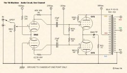
Can you post the schematic you are using?
There have been a few different versions of the MM, so your build may not be exactly the same as the circuit shown in the attachment to Post #1.
When you say that you 'tested the tubes', how did you do that?
I built a 'Machine' some years ago and recently sold it; now I'm thinking of building another one, so I may have the same experience as you!
You checked the "continuity" of the tube in the circuit, in a powered state??? As for the -8.4V on the plate when you connect the cathode leads me to think that the ICXPM45S CCS is possibly shorted. If so, that would put the cathode at approx -60V, grid being at ground potential (0V), which would bias the tube on strongly causing it to pull high current, with the resulting voltage drop across the plate resistor(s).So...
I have no experience with the 6GK5, lots with the 12A-7 type, I just tested the tubes and I get continuity over GRID and PLATE (2 and 5) on ALL THE TUBES!
Surely that cannot be correct, this is in both powered and unpowered states!
Cogsncogs you nailed it! The IXCP10M45S is shorted, however it must be an internal short as there is no possible way it can be shorted anywhere else, and it is on both channels so it could just be bad packages.
I ordered them from Ebay, mouser now have them in stock so I have ordered some from there a couple of euro each, although I have some DN2540N5 I could cascade, but I think I am happy to wait.
This project has been a journey, however I have learned a lot, and good math will not get you out of all problems, I need to be a bit more practical.
Tack
Björn
The earlier versions of the MM didn't use the IXCP10M45S, just a dropping resistor.Cogsncogs you nailed it! The IXCP10M45S is shorted, however it must be an internal short as there is no possible way it can be shorted anywhere else, and it is on both channels so it could just be bad packages.
You could try experimenting with that idea while waiting for your replacement parts.
Attachments
Glad to be of some help.Cogsncogs you nailed it! The IXCP10M45S is shorted
")
Hi All,
Thanks for your help so far, I now have a beautifully sounding SE amp.... Let me explain.
So, I seem to have a coupling or decoupling depending on how you look at it issue, on the cathode of the input driver, I get a signal in phase with the input, or at 0 degrees lets say, on the plate I get a signal that is 180 degree out of phase, it is super, on the second driver the LTP is working great until it gets to the plate, then.... the signal from the input driver tube is passing through and the signals are in phase, so when the signal gets to the EL34 tubes they are in phase, this obviously gives no (well very little) output, as they are just canceling each other out in the tranny.
How I know it is the plate the signal from the input driver is if I disconnect the signal to the cathode of the 2nd 6GK5 I still get an in phase signal going to the EL34 on both signal paths.
Does there need to be isolation? I have taken separate tails from the supply (360VDC) and after the plate resistor I get spot on 135v, on both, it is really weird.
I am sure that this is just a rookie mistake, I was genuinely thinking about just using on of the 6GK5 as a gain stage then using the next as a cathodyne inverter, but that feels very much like a fail.
My CCS is working great as well, I get good resolve class A SE mode, great bass and sound, but if I want a SE class A amp I would have built one!
As always, any help is greatly appreciated!
Tack
Björn
if I disconnect the signal to the cathode of the 2nd 6GK5
I don't understand what you mean by 'signal' in that statement.
It seems to me that the input 'signal' connects only to the grid of the 'upper' tube...
Are you sure you don't have a wiring mistake somewhere? It's not a very complicated circuit; perhaps a wiring error could have been the problem with your CCS earlier?
The input to the second 6GK5 is effectively to its cathode, via the cathode of the first 6GK5 as bjornaudio states, with the grid grounded (assuming no global feedback connected). If you disconnect the cathode of the second 6GK5 and still get a signal from the anode, then maybe you have inadvertently connected the two anodes? Especially as you are measuring exactly the same voltage at each anode. Just measure the resistance between the two anodes (with everything off....) and you should just see the two anode resistors in series.
Hi All,
Thanks for your help so far, I now have a beautifully sounding SE amp.... Let me explain.
Can you take some clear pictures of your wiring scheme and post them here?
Stupid question...
In the schematic shown in the first post of the thread, both secondaries of the Amveco 62035 are wired in series to provide 44 VAC to the bridge rectifier. This subsequently provides -66 VDC to the CCS of the first stage and the -22 VDC bias for the outputs. I can understand how the -22 V bias is created, but where does the -66 V come from? According to my beer math:
44 V * 1.414 = ~62.2 V
Obviously I'm missing something, as several folks have built working amps to this very schematic. Where does the extra -3.8 V come from?
Mr_Zenith,
Perhaps the extra voltage comes from a secondary that was rated for 2 Amps for example. But that 44V secondary is so lightly loaded, that it is now more than 44V.
Otherwise, we have the math problem you mentioned.
I have a 6.3VAC secondary that puts out 6.9V under light load.
Also, I have lots of transformers that are rated for 115V, 117V mains.
My mains run from 117V to 123V.
As to the secondary voltage . . . what would you like it to be?
(I always run the load on the filament secondaries at a fraction of their rating;
and I use choke input B+ filters, so the (I)squared heating of the B+ secondary is far less than if I used a cap input B+ filter).
Run the parts of your amplifiers at conservative ratings.
Get good reliability and long life out of capacitors, transformers, and tubes.
Push parts to the limit, and . . .
Your Mileage May Vary
The choice is yours.

- Status
- This old topic is closed. If you want to reopen this topic, contact a moderator using the "Report Post" button.
- Home
- Amplifiers
- Tubes / Valves
- 6v6 music machine build help!