Some pix on the beauty, Hows your workbench btw?
Nice photos. The Wavetek is highly regarded till today and some dealer refurb samples with recalibration are listed for top dollar even.
I got 12MHZ arbitrary function generator, one very modern DSO, one vintage German CRO, 2x5A 30V floating & configurable bench PSU, OKI Metcal Iron, 4 DMMs the two of them are Fluke, 1 LCR 0.25% meter, EMU box for FFT, WT3 Dayton, 2 cal mics and cal mic pre, SPL meter, bunch of BNC cables, 350 & 100 MHZ probes, silicon jacketed power cables, various hooks, feedthrough terminator, ESR meter, hot air station, bunch of various parts, breadboards, desk crane mag lamp, that's what I can remember from top of my head.
Pot max volume = zero resistance in series to the grid so the BW should be at its max. When pot is at low listening volume the BW should shrink. But never a slope in audio bandwidth across the full rotation.
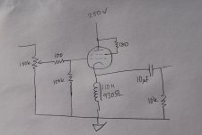
Btw I have a 100 k gridleak also, I should post a schematic maybe.
You should not get any attenuation in the audio band. That cathode follower thing has way too wide bandwidth on any setting if working normally. See if you need some gate stopping when the pot is at max and presents no additional series damping. Check your measurements again. Showing 1.5MHZ at one position and then a dip in the audio range at another does not compute. Or its some trouble happening. Set your ref pk-pk at 6 divisions. When falling to 4 divisions its roughly -3dB. That will help you sweep fast the gen knob and spot the BW limit fast in all vol pot positions.
Thanks. It was a bit of a joke over my disorder. I should complete that workbench b4 jumping on projects but I cant stay away. So, back to my downhill slopes, you say its like life or should I do some other measures?
I don't have room for dedicated lab, I combine my computer desk so I must relocate stuff back to original places when I stop experimenting or servicing on something, which is a pain. Maybe you did not account for X buttons on the Wavetek and you are on a higher band than thought?

OKI Metcal Iron,
How's that iron been doing in your hands so far?
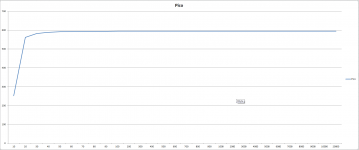
New graph 100 k load pot on max
That is with the internal Pico gen I guess. OK, I see no problem.
How's that iron been doing in your hands so far?
Good for my power needs. The one Stajo and you have is very good also. Yours are classic sensor and temp set so you can comprehend and adapt fast for tips.
Something is fishy. I added 100k on the output that already had 10k which ends me up to 9k9 and I have a straight line. What am I doing?
You are doing things you do for first time fast. Take your time.
Good for my power needs. The one Stajo and you have is very good also. Yours are classic sensor and temp set so you can comprehend and adapt fast for tips.
Mine is mighty fine for my needs too. I just remember eyeing used classic metcals and got curious. Need to source a new solder spool, though.
Yes your right I should contemplate and remeasure but now all systems are go right? Or should I get other measures?
Suggest me a good output leak/load.
You should get no other measures than a logically high output resistor (much higher than the amps you gonna drive) if your measurements are confirming OK response and squares after revisiting the procedures in good control. Check that your vintage Wavetek has no intermittent buttons or pots that may drop its Vout suddenly at times. When you see weird dip, measure the gen output with your UNI-T DMM that I saw a glimpse of in your photo. If its the 61E I just measured its reliable for AC RMS up to 100kHZ for one digit after the decimal dot at 2V.
Thanks. I dont know why I'm building and what for actually. I think I'm just in it for curiosity. Learning.
This wonderful session has made me curious about measurement so I just downloaded ARTA. I think I am interested in knowing what is behind why I hear what I hear.
One thing I will need to feed soon is this http://www.diyaudio.com/forums/pass-labs/169323-semisouth-donuts-8.html#post3440081. I am waiting for parts. My first sandbuild maybe.
I could move up the chokes to the anodes maybe.
- Home
- Amplifiers
- Tubes / Valves
- 6V6 line preamp