Hi, I have completed the 6V6 line amp built, indeed the sound is big!
I have used Salas' standard line circuit with a 6L6GC shunt regulator. Using the parts that I have, B+ is 292V, 18mA through the circuit.
Thanks Salas!
Hi, I would recommend you use a higher load value in these conditions. Try adding 2.7K 3W-5W resistor in series to the 5K anode load one and tell us if it got better or not. Pictures would be nice too.
Still listening to mine every day. I've since
changed the B+ regulator to a 6V6 shunt
regulator with DC heaters dialed in at 340V with a larger
transformer. My amplifier can reach full
volume without Salas' pre but it sounds
lifeless. Thanks again for this beautiful
design Salas
changed the B+ regulator to a 6V6 shunt
regulator with DC heaters dialed in at 340V with a larger
transformer. My amplifier can reach full
volume without Salas' pre but it sounds
lifeless. Thanks again for this beautiful
design Salas
I have been messing with the circuit today and have learned a few things -
I have got some hummm, but I think it's a wiring problem. It goes away when the pot is turned all the way up or down, and worst at the mid-position.
I think I also have some filament hum, as they are AC for now. I will put together a quick and dirty regulator for them tomorrow.
My 6V6 pre works fine AC heated, perhaps you should have a look at the routing of your wiring?
Here's a pic I made for someone else, suffering from grounding issues. Maybe it's to your service.
An externally hosted image should be here but it was not working when we last tested it.
Tinitus: The RCAs must be isolated from a conductive chassis indeed.
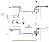
Would you break up the signal ground and take it to the star directly?
Roberto: In reality the lines you made red are one and the same. Starground(s) and chassis connection is made to the capacitor that has the lowest ripple current to keep large loading currents from the ground. Star topology is used to prohibit larger currents to interfere with smaller currents. Exhaustive runs of grounding cables seem to work contra productive, possibly because of the extra inductance.
New scheme:
Attachments
Would you break up the signal ground and take it to the star directly?
I suppose thats the point of having a starr ground, if there is one
though I prefer to look at it like multiple starr gounds, along the same string
often you see tube amp builders have one(and only one) solid core wire going through the whole amp, for all ground connections
and you often see the signal ground isolated from chassis/earth by a small resistor, or maybe a thermistor(look at NelsonPass DIY)
Not much difference to the way we configured it as you now got it. Don't bother much. Just order Mills 7.5K MRA-12 anode resistor for substituting the combo resistors you now use, when able. Is there a schematic you can post of the tube reg you use, and some pictures of the preamp if possible?
I have a question about the power supply ...
I plan to use :
transformer = 2X310 (150ma)
tube 5RaGY
c1 = 4.7u
L1 = hammond 193C (20H / 100mA / 181ohm)
c2 = 160uf (2x80uf 800VDC parallel motor run caps)
psud ends with 65mA load (SSHV2 will be used, 2 regs as per Salas suggestion) and gives around 341 b+ ...
hows that sound ?
other option, CLCLC
c1=4,7
L1,L2 = hammond 158q (5H/150ma/105ohms) or 157Q (3,5H/125ma/98ohms)
c2,c3 = 80uf motor run
psud b+ is 338 ...
5R4GY says 4uF in the RCA manual. Are the chokes resistive parts added? Those will drop some little voltage.
you are right (datasheet says 4uf), I'll rerun psud with c1 =4uf,
for the chokes R, you mean added at psud sim ? yes they were added ..
There is the 3u9 standard value to use. Yes, the parasitic choke resistance is what I meant. Which is good because the valve DHT rectifier needs some damping for peak currents. 5R4GY is amongst the best for tone that I had used, but ducks its head the most for voltage loss and its a bit fragile for current delivery.
Its about time to place some orders for the missing parts ....
*I am going to use one chassis, for the tubes there will be a subchassis with some damper vibrators I saw at the 26dht linestage thread (4x Anti Vibration Damper Isolator for FPV Aerial Photography GIMBAL ECILOP XA650 | eBay) plus rubber grommets , I hope they will be fine ...
*I am going to use one chassis, for the tubes there will be a subchassis with some damper vibrators I saw at the 26dht linestage thread (4x Anti Vibration Damper Isolator for FPV Aerial Photography GIMBAL ECILOP XA650 | eBay) plus rubber grommets , I hope they will be fine ...
Do make sure you use the proper sized input (first) capacitor with a tube rectifier - you can easily make it too big and damage the tube. No more than 10uf, perhaps less.
5R4 are very nice, and also quite useful if you need to throw away voltage easily - they have a 60v forward voltage drop.
5R4 are very nice, and also quite useful if you need to throw away voltage easily - they have a 60v forward voltage drop.


Nice, thanks. Effective solutions for box space and cost. Congratulations for finishing it. Those green Russian output capacitors were marrying happily with FT-3 0.1uF Russian Teflon bypass in some older experiments I did, maybe you can try if you got any. I should see to run a spice sim about the 6L6GC & TL431 schematic if I can get the models. Is the heater reg voltage source or current source?
What amp and speakers you drive with this preamp? What you had before in its place?
What amp and speakers you drive with this preamp? What you had before in its place?
- Home
- Amplifiers
- Tubes / Valves
- 6V6 line preamp