$130 for the pair. Expensive, if just building another amp, but i like this one enough that it will stay. Consider also that the match, and build quality are much higher without any doubt. Obvious that these were the creme of the crop, bein gmiltary version, in a time of the pinnacle of tube making. My brother has always been a NOS guy and i though ti twas just fo rspenin gmoney and bragging, but new tubes cant rouch these things. They plugged perfectl yinto your schematic with no filamen ttweaking or anything else needed. My brother, a long time tub enut, will be dropping by to give a lsiten. He has heard everythin gi have built and i am interested to hea rwhat he has to say about this combo. Your pre adds just th erigh ttouch of bloom and space, fo rlack o fbetter words, to my BA3 power amp. Wonderful combo. Next is finishin gthe new tube psu. Just scored a Hammond 193 Q, 10H and 500mA pooted choke for CLC. Cant wait. I will be tryin gother schemes using new Tungsol(excleent buy an drecommendation, BTW). Perhaps choke loaded and even balanced version. Thanks again Salas!
I'm using the Russian 6n6c and I really like the sound. I've got a dozen or so used but good 6V6's (RCA etc.) but these are my favorites so far. I'm driving a Bob Latino ST-120 that I put together a while back. Many many thanks to Salas for this excellent design. I built it as per post one and have probably 50 hours on it. Just keeps sounding better.
Yes sir. Sounds better than it looks. I actually salvaged the PT from a Korean era US Navy receiver. Most everything else (Mundorfs etc.) were as per your design.
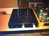
Fine, as per total schematic. I see 4 golden screws around each tube also. Are there resiliently hanging boards off of those?
Any changes to bias settings using 6n6c? Any specificruusian brand.
Haven't checked the bias yet. Couldn't really find what these tubes require. Everything is running very cool. I'll check it when I get home and let you know. These are from "the bay". Price was outstanding.
Fine, as per total schematic. I see 4 golden screws around each tube also. Are there resiliently hanging boards off of those?
You are correct. The sockets are mounted on separate 3"x5" one sided pcb's. There is a rubber isolation mount on each corner. I also put a bead of hi-temp silicone around the socket mounting hole. I then mounted the socket against this (after it cured).
I'm getting 15.61V and 15.73V on the cathode resistors. This puts it very close to the 6V6's I've had in there. I've got the data sheet for the tubes but it's in Russia. I'll try to translate it and see what the tube actually needs. Readings are with exactly 340V from the HT supply. Btw tubes came in yellow boxes.
Exactly. Tube has OTK 4 with 31 inside a diamond and 11 75 (date code?) on the glass envelope.With some ''RADIO'' like ''ΡΑΔΗΟ'' print?
Had used those too, still in my inventory. But in a USSR civilian marking. Melodic sound, one of my favorites. Some turned noisy after a few weeks from a batch a friend got back then. But the majority continued OK.
So, being aMerican, there is no such thing as too big. But.. after buying this thing and getting it in, i think it is bigger than anything i have seen. Is there such a thing as too big.
Completely different topic; when running the 6v6 as a triode, you have a resistor wired to the screen. According to the datasheet, when connected as a triode, the plate resistance drops significantly. Is this the result of the screen resistor being in parallel with the plate resistance reducing it and effectively changing the response
Completely different topic; when running the 6v6 as a triode, you have a resistor wired to the screen. According to the datasheet, when connected as a triode, the plate resistance drops significantly. Is this the result of the screen resistor being in parallel with the plate resistance reducing it and effectively changing the response
Attachments
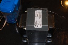
Massive.
The screen grid shields the control grid to the anode and ups the efficiency. Higher Mu gives higher impedance and low Miller. So you get the curves leaning to the right almost parallel like in a Mosfet. When you short the screen to the plate (the small value resistor there is to suppress oscillations), you get back to triode like square law(ish) curves, lower impedance, but 1/3 the efficiency and you drink a shot at Mr. Miller's bar.
The screen grid shields the control grid to the anode and ups the efficiency. Higher Mu gives higher impedance and low Miller. So you get the curves leaning to the right almost parallel like in a Mosfet. When you short the screen to the plate (the small value resistor there is to suppress oscillations), you get back to triode like square law(ish) curves, lower impedance, but 1/3 the efficiency and you drink a shot at Mr. Miller's bar.
- Home
- Amplifiers
- Tubes / Valves
- 6V6 line preamp