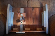
Very nice case Buzzforb, congrats. Any chance to see some pics of the inside? Just to understand how it's made.
MOre bracing will be added. Tube sockets are mounted on PCB and attached to wood with vibration grommets.
Salas,
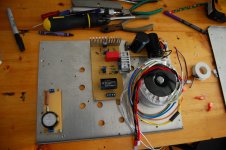
how do yo like the custom heatsinks. Pretty pityful!

Will probablly rearrange things for better star ground potential. I need to redesign SSHV2 into smaller footprint so that I can fit two boards plus trafo and still keep away from signal wires. Happy to find that trafo has a shield wire.Should help with noise. I will probably put trfo in seperate case with tube rectifier and small cap and have smaller trafo in case for filament supply.
Salas said that you can get away with 47uF for prefilter if using SSHV2, so i will be changing to film only psu after i get it up and running.
Attachments
Last edited:

Is the IRF840's heatsink all that is in the pic? Or its gonna be attached to something augmenting it? Looks small for the job as is. DN2540 needs insulation. Its the first one in line with high voltage raw dcin that dissipates enough. The one it cascodes underneath it needs no sink. Their drains should not touch together through common metal.
All three fets are insulated. f the HS is too small, I will figure something else out. The 840 is sandwiched between two pieces of aluminum. One 1/8" L and the other is 1" square with pretty teeth cut in it. I am bout to fire up the sshv2. Gonna read your write up again. Should the pots be set to zero and slowly brought up. With pots set to zero, shouldn't some voltage still appear across 10ohm test point?
Set current's pot to 1/4 towards zero, voltage pot to 1/2, use a dummy load for simulating nominal consumption of destination load circuit. Bring up current pot first to nominal load current plus 20mA. Then bring Vo pot up to nominal. 0.5V across test point means 50mA total current, 0.6V means 60mA, and so it goes for indication.
somone suggested 15k 5w in the SSHV thread. I dont have anything like that. What are some alternatives?
3 of 2W 15K in parallel.
How about 6 2W 68k paralleled?
5 would be better.
Why are tubes with big grids/anodes more prone to ringing in preamp duty than when used as output device?
In one case ringing is amplified by output stage, in another case it is not.
3 of 2W 15K in parallel.
Oops... Sorry, I miscalculated - I thought you need 5K.
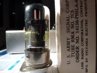
They are described as electrical equivalents in old datasheets indeed. I would use an adapter for those though so to have the octal standard on the pre-amp for exchanging makes. 7C5 to 6V6 Tube Adapter
- Home
- Amplifiers
- Tubes / Valves
- 6V6 line preamp