Short answer for cathode resistance- as shown in this thread with this circuit you are only likely to see 1/3~1/2 watt dissipation there, so the 2w resistor outline here should be plenty of leeway to oversize the part for cool running. I suppose I could oversize it and add some cooling holes under it to be safe?
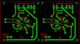
For the input/output spacing, they each have a ground pin between them at the terminal strip and don't run parallel to the edge of the board. I don't believe they will couple to each other. Think we should swap places on the in/out?
For the supply voltage traces, well, I suppose we could work in a separate cap for each channel, and a separate supply trace as well, but with 1-1.5mm wide traces I'm not so sure it's needed for the combined 40-100mA draw that this circuit will use. However, I'm looking forward to further comments on this. I personally don't think that it's needed if the power supply is competently arranged but I'm not an expert")
For the input/output spacing, they each have a ground pin between them at the terminal strip and don't run parallel to the edge of the board. I don't believe they will couple to each other. Think we should swap places on the in/out?
For the supply voltage traces, well, I suppose we could work in a separate cap for each channel, and a separate supply trace as well, but with 1-1.5mm wide traces I'm not so sure it's needed for the combined 40-100mA draw that this circuit will use. However, I'm looking forward to further comments on this. I personally don't think that it's needed if the power supply is competently arranged but I'm not an expert
Last edited:
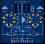
Initial layout of sockets, 4mm mounting holes, it'll have a ground plane with large clearances between traces and copper pour. Nice wide traces is the plan. I went ahead and put corner mounting holes as well as one on either side of the sockets. Does 4mm sound like enough? I think I usually see M3 holes on most other gear.
I figure a resistor between plate and screen will be a good idea, so maybe that works? I'll do the initial layout based off of the schematic posted by Salas, and then I'll add extra pads here and there as could be useful. I like PCBs with extra pads for experimenting anyway. You could even use this PCB for an SE output stage if you wired a transformer in instead of the load resistors
I like where you're going with the tube saddle holes.
I like tube mounting holes on the PC board that line up with the tube saddle for undermount saddles. Belden makes a PC pin socket that also has a saddle. I recently mounted a socket on female/female standoffs on the board by the saddle. one screw through the bottom of board into the standoff, another screw through the top saddle into the standoff, then solder the socket in place. Now remove the top two saddle screws, presto, the saddle now has a solid threaded insert! now the whole board holds itself onto the chassis by the tube saddles alone and a threaded means to mount the saddles is built into the board, no nuts needed, just screws from the top, no need to hold a nut on the other side either! This also eliminates 4 extra ugly screw heads from the chassis topside you'd have if you do a corner mounted PC board, too many screw heads for me.
I think moving those traces is a good idea for sure, gets them more straight to the terminals. I'll also bring R1/R6 and R11/R16 up and closer to the center of the board. This will let us bring the output capacitor outlines further away from the output terminal strip for more room.
Stand by...
Stand by...
Last edited:
Alright, last post's suggestions by PKI incorporated. Cleaned it up a bit for sure! Also, FYI, mounting holes are M3 now.
EDIT: also moved everything up a bit, now more real estate for capacitors at the bottom.
EDIT: also moved everything up a bit, now more real estate for capacitors at the bottom.
Attachments
Last edited:
Initial layout of sockets, 4mm mounting holes, it'll have a ground plane with large clearances between traces and copper pour. Nice wide traces is the plan. I went ahead and put corner mounting holes as well as one on either side of the sockets. Does 4mm sound like enough? I think I usually see M3 holes on most other gear.
I figure a resistor between plate and screen will be a good idea, so maybe that works? I'll do the initial layout based off of the schematic posted by Salas, and then I'll add extra pads here and there as could be useful. I like PCBs with extra pads for experimenting anyway. You could even use this PCB for an SE output stage if you wired a transformer in instead of the load resistors
Alright, last post's suggestions by PKI incorporated. Cleaned it up a bit for sure! Also, FYI, mounting holes are M3 now.
EDIT: also moved everything up a bit, now more real estate for capacitors at the bottom.
Lingwendil,
Its going great! If others agree can you make sure the tube socket saddle hole spacing center to center matches a current production tube socket like Belton? Belton makes a fine socket, its widely distributed and not expensive. I've attached the ,mechanical drawing for the Belton octal sockets that have PCB pins and saddles. Would this be ok?
It looks like the saddle holes should be 40mm center to center. I'll be glad to buy some boards.
View attachment VT8-PTS.pdf
Last edited:
Hey Ling? There's space for a 7 pin socket inside the 8 pin. This way you could use 6V6 or 6AQ5 with one board. If the 9 pin fits inside, the 6P1 could be outlined. If you add a screw terminal to pin 3 for top cap, you can use sweep tubes like 6BQ6B, too.
yes 7 pin sockets fit the same pad hole spacing as an octal, but would the pin functions align?
The pins should align well enough if you change the angle of the 7 pin socket to align the plate pins.
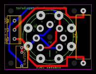
I did a similar thing for this bias shut regulator. You can use 8 pin or 7 pin VR tubes.
I did a similar thing for this bias shut regulator. You can use 8 pin or 7 pin VR tubes.
Attachments
Last edited:
Lingwendil,
Its going great! If others agree can you make sure the tube socket saddle hole spacing center to center matches a current production tube socket like Belton? Belton makes a fine socket, its widely distributed and not expensive. I've attached the ,mechanical drawing for the Belton octal sockets that have PCB pins and saddles. Would this be ok?
It looks like the saddle holes should be 40mm center to center. I'll be glad to buy some boards.
View attachment 942264
Let me take a look at the current hole spacing, but that shouldn't be a problem at all to set them at 40mm
For those that are interested in boards, don't start "putting orders in" just yet. I don't want to get the thread too cluttered up with much more than the development of the board at this time. Files will be available for anybody that is interested to have some made once tested out. I'm not sure if I am able to personally handle the sales and dispensation of PCBs time wise, so I'm not committing personally to anything yet.
As to the seven pin sockets, let me look at them and see how the pinout goes. It's been years since I touched one.
The pins should align well enough if you change the angle of the 7 pin socket to align the plate pins.
I did a similar thing for this bias shut regulator. You can use 8 pin or 7 pin VR tubes.
Yeah 6AQ5 is very enticing if it could be a dual tube board without too much compromise. It might be worth selecting 2 or 3 6V6 family tubes and maybe etch the board with some key jumpers instead of hard traces for those pins only that don't align functionally.
Update: Wavering DC offset
I finally tried AC coupling the amp and that took care of the wavering DC offset. No more woofer pumping even with a 27 micro farad cap on the preamp output which sounds awesome to me.
Thanks for the help.
Congratulations

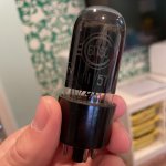
Any pictures of the preamp build you can post?
- Home
- Amplifiers
- Tubes / Valves
- 6V6 line preamp