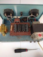
Yes indeed, I found this in the trash outside a microbiological laboratory.
Old days instruments.
What first come in mind was to salvage the analog meters but final i prefer to keep as h.v power supply.
Have you opened it? Has any marks of the OEM? What main elements does it use? It could be asking for some maintenance work.
Have you opened it? Has any marks of the OEM? What main elements does it use? It could be asking for some maintenance work.
Yes i had opened it in the past but I did not decide whether to keep it or to keep the meters only.
A maintenance work is certainly necessary.
Now i have another solution for the preamplifier powe supply.
A regulated power supply from another preamplifier.
I will post latter, together with the inside view of this old unit if it is any interesting.
Last edited:
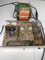
The new power supply.
An old Elektor preamplifier arownd pcl86, and an old giant transformer salvaged from a Grundig color t.v,from the trash of course!
An old Elektor preamplifier arownd pcl86, and an old giant transformer salvaged from a Grundig color t.v,from the trash of course!
Attachments
Last edited:
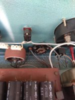
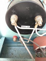
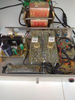
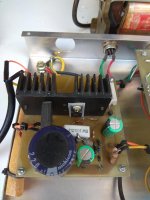
What is inside.
Dosen't have any active elements somewhere? That 500R pot is a monster, it looks like a mini Variac. The meters are KYORITSU Japan but its Greek main transformer brand logo tells it wasn't an imported OEM unit but some local OEM was assembling those units.
The new power supply.
An old Elektor preamplifier arownd pcl86, and an old giant transformer salvaged from a Grundig color t.v,from the trash of course!
Confirming the idiom, one man's trash is another man's treasure
")
It is time to put my hand on this simple version.
Nothing special here, just to try things.
I have so many used 6v6 so why not.
No good looking but playing nicely.
Good work Salas, very good!
The power supply!
A generic power supply that I picked up from the trash!
Looks dangerous... is it ?
Never really realised until recently, but I think a lower voltage variant of this could be done with the 6P43P-E in triode connection. It's a stunningly linear tube at low voltage, and the mu would be very similar to the 6V6 version with a bypassed cathode.
Curves from here-
Tube Tester Files - EL82, EL84, EL86 Soviet Clones
Maybe a simple isolation transformer for a raw ~160 volt supply, a simple mosfet ripple filter, and a small filament transformer could make a nice little variant. -5~ volts grid, 100 volts plate, ~60mA... Maybe I should cook something up
Attachments
Last edited:
Maybe a simple isolation transformer for a raw ~160 volt supply, a simple mosfet ripple filter, and a small filament transformer could make a nice little variant. -5~ volts grid, 100 volts plate, ~60mA... Maybe I should cook something up
How about a 60V B+, 30V plate. 16ma current since it's just a preamp tube and doesn't need to make much power?
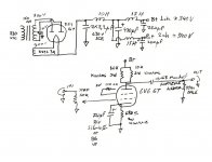
Hello guys and gals. I'm planning on building this preamp from scratch. Meaning I can buy the parts in the schematic as designated rather than build it from parts I already have. A couple of simple questions from a novice but not a complete novice. First questions:
1) What does V1 and V3 represent on this schematic?
2) How does this schematic compare with the one on page 1 think I'd like to build it in it's basic form while leaving room for the filament regulators as well as the CCS. Does this make sense? Some of the resistor and cap values are different.
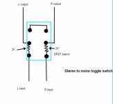
3) Any suggestions as how to implement source selection, balance in addition to volume control, mute and mono?
Thanks in advance. And I apologize for bringing this thread down to a simpleton's level!
Dave
1) What does V1 and V3 represent on this schematic?
2) How does this schematic compare with the one on page 1 think I'd like to build it in it's basic form while leaving room for the filament regulators as well as the CCS. Does this make sense? Some of the resistor and cap values are different.
3) Any suggestions as how to implement source selection, balance in addition to volume control, mute and mono?
Thanks in advance. And I apologize for bringing this thread down to a simpleton's level!
Dave
Attachments
Last edited:
Why did you select the 5R4GY for the rectifier? It was developed for the military & R&D, rated for operation at 40,000 ft. Unless you already have one there are better tubes for less $$ to do this function.
The 5V4G would be better, slow warmup & lower forward drop.
Another alternative is the 6X5GT. The H-K rating is 450 Volts so that doesn't require the extra 5V heater winding on the power transformer. And it even looks like a 6V6GT.
Try for simplicity, don't be burdened by extras not required to make your circuit operate.
WntrMute2 -
1) That's a SPICE schematic. They are voltages for the simulation to work. V1 is the input signal, V2 is the B+ supply voltage.
2) You want to build the one in post #81 - 6V6 line preamp
3) Add a switch in front of the pot(s);
the easiest and best way to do balance is have 2 volume pots, one for each channel;
Mute requires a SPST for each channel (Or one DPDT);
and I'm not sure abut mono. How many mono records do you have?
Why did you select the 5R4GY for the rectifier? It was developed for the military & R&D, rated for operation at 40,000 ft. Unless you already have one there are better tubes for less $$ to do this function.
I already had one then (2007). So I was either fitting that one, some 5U4G versions, and a GZ34. Those three types were noted on the schematic Mr. 6L6 linked in his post just above.
This video I just quickly found on YouTube futures representatives of those three rectifier types for anybody non familiar to see:
YouTube
I have a few hundred mono records. I'd like to do a separate volume and balance control preferably.WntrMute2 -
2) You want to build the one in post #81 - 6V6 line preamp
3) Add a switch in front of the pot(s);
the easiest and best way to do balance is have 2 volume pots, one for each channel;
Mute requires a SPST for each channel (Or one DPDT);
and I'm not sure abut mono. How many mono records do you have?
Thanks for your help!

- Home
- Amplifiers
- Tubes / Valves
- 6V6 line preamp