i am not sure if the gain is high enough for that kind of negative feedback, adjustment of feedback is pretty easy tho on a Williamson, just one resistor to play with.
Don't forget stability and feedback in global feedback systems go hand in hand. Stretching with Higher feedback ratio's often try to impose wider bandwidth given the amount of loop gain available.
The whole issue of stability and Nyquist is over many heads but generally I do the simple phaseshift and Bode map to ascertain any creepage to 180°. After having done many amps one gets the feel of expected gains and can instinctively work it out.
To do the job proper one has to go down this avenue. In the illustration, this example illustrates the concertina coupling caps in a Williamson must not be arbitarily chosen !
This is where a trade off is required versus LF distortion, tailoring off loop gain at the lower end and transient response. OMO; Williamson went too far with these high coupling cap values in the quest for low distortion at the LF end, hence many quotations mention the design bordering on LF oscillation. Don't blame the PSU in this one.
If one has worked in the MI design industry, one will tell you that LF THD isn't so important, but H2 is the one that everyone likes. Many amps do have too high values of interstage coupling caps which sounds very tight. Checking my GEC 88-50 amp, at 30Hz/50W the LF THD is 1.7% and gradually drops to 0.2%around 400Hz and rises again at 10KHz. So there is a bathtub curve.
Remember the Quad II; MJ 4th edit (1st edit) c harmonic comments regarding output transformer. All relevant stuff...read it.
richy
Attachments
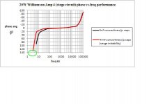
Yes, DTN Williamson recognised his initial error and corrected the coupling cap values in the revision in his letters to WW. For those without immediate access, he notes that the output transformer's primary inductance varies with signal level and its pole cannot be allowed into the same region as the dominant coupling RCs' pole. (Yes, "pole" isn't the correct term; pace). He recommends staggering the RC couplings' poles by a factor of 4 or 5, and letting the second one dominate. This gives the shortest "hang time", clipping overload recovery time, because clipping is typically at the output valves' grids. The dominant pole must remain above that of the output transformer primary at full output signal.
All good fortune,
Chris
All good fortune,
Chris
The RC values in the OP's circuit (has it mysteriously changed?) look about right to me.
Thanks,
Chris
what values in the circuit?
some of them are just placeholders.
Last edited:
what values in the circuit?
some of them are just placeholders.
Coupling caps + grid leak resistors. Time constants look fine by DTNW criteria.
Thanks,
Chris
Rubin -
I was working on something like your project a while ago and got diverted with a simple amp.
The link below has what I was heading towards, octal's (6SN7's) and a quad or more of KT88's
http://www.diyaudio.com/forums/tubes-valves/217019-ez125-amp-project.html
The part values are not accurate at all and just tossed them in as place holders. The circuit is not mine by any stretch, but a mashup of a couple of amps I liked.
Power supply will likely get a revamp as well, again, all of this was just a very first pass to get a schematic into the system. I have not worked on it for months, but once I wrap up an the almost finished EZ10 project I'll be jumping back on it.
I'll likely build a PCB much like I did for the EZ10 and EZ260 as I like doing PCB's so will be not what some folks like but hey, I'm not building it for them
Sandy
Rubin -
I was working on something like your project a while ago and got diverted with a simple amp.
The link below has what I was heading towards, octal's (6SN7's) and a quad or more of KT88's
http://www.diyaudio.com/forums/tubes-valves/217019-ez125-amp-project.html
The part values are not accurate at all and just tossed them in as place holders. The circuit is not mine by any stretch, but a mashup of a couple of amps I liked.
Power supply will likely get a revamp as well, again, all of this was just a very first pass to get a schematic into the system. I have not worked on it for months, but once I wrap up an the almost finished EZ10 project I'll be jumping back on it.
I'll likely build a PCB much like I did for the EZ10 and EZ260 as I like doing PCB's so will be not what some folks like but hey, I'm not building it for them
Sandy
what benefit will you get from setting up that 6sn7 driving the k88s like that.
why use 3 6sn7's? is it necessary?
Rubin -
My understanding is the Cathode Follower is useful for driving low impedance loads, my guess is that driving paralled output tubes this is a good thing. (Others feel free to chime in with pro/cons of CF in the driver).
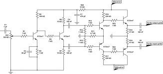
Also check out the T-Rex amplifier. You should be able to find it here on DIYAudio, it is a 6SN7/KT88 build that looked to be well thought out. I have the schematic attached.
Sandy
My understanding is the Cathode Follower is useful for driving low impedance loads, my guess is that driving paralled output tubes this is a good thing. (Others feel free to chime in with pro/cons of CF in the driver).
Also check out the T-Rex amplifier. You should be able to find it here on DIYAudio, it is a 6SN7/KT88 build that looked to be well thought out. I have the schematic attached.
Sandy
Attachments
Ah, a Williamson. That certainly is a time-tested classic.
I've always wondered if it would be an improvement to replace the V2 6SN7 with something like a 5687 or a 6N6P, with a much lower rp (for lower output impedance).
There's another circuit that's kind of interesting, but requires a negative supply for the first stage. A version of it appeared in Sound Practices magazine, and was called "Tubesaurus Rex." Schematic attached.
--
Attachments
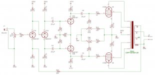
pretty much a simplified version of the GEC PPP 400watter.
doesn't the last valves filament need to be raised to cathode levels?
another thing, this circuit whould run the same regardless if there are 2 pairs on the output, or 4 pairs. just with reduced output power, (if transformers are adjusted) Kt88 tubes ofcourse.
doesn't the last valves filament need to be raised to cathode levels?
another thing, this circuit whould run the same regardless if there are 2 pairs on the output, or 4 pairs. just with reduced output power, (if transformers are adjusted) Kt88 tubes ofcourse.
Attachments
No, they can handle a certain amount of voltage between cathode and heater. Look in the datasheet. On the other hand, it is a good idea to raise all the valve heaters to somewhere between 1/4 and 1/3 of the supply voltage (plenty of references around).
In my opinion, this circuit can drive more than one pair of KT88, due to the low rP of the 6SN7.
By the way your valves look... strange
In my opinion, this circuit can drive more than one pair of KT88, due to the low rP of the 6SN7.
By the way your valves look... strange
No, they can handle a certain amount of voltage between cathode and heater. Look in the datasheet. On the other hand, it is a good idea to raise all the valve heaters to somewhere between 1/4 and 1/3 of the supply voltage (plenty of references around).
In my opinion, this circuit can drive more than one pair of KT88, due to the low rP of the 6SN7.
By the way your valves look... strange
oh silly me forgot to swap out the transistors for a triode pic.
the program im using doesn't have tubes, so why not just use the transistor symbol instead
circuit lab is nice for being browser based with online save and PNG convertion.
i am thinking 2 pairs, (4 valves) might add more but might be risky since im going to swap between triode and UL mode.
pretty much a simplified version of the GEC PPP 400watter.
doesn't the last valves filament need to be raised to cathode levels?
another thing, this circuit whould run the same regardless if there are 2 pairs on the output, or 4 pairs. just with reduced output power, (if transformers are adjusted) Kt88 tubes ofcourse.
The GEC PPP 400 watter looks to be a Williamson with cathode followers after the push-pull driver.
--
The GEC PPP 400 watter looks to be a Williamson with cathode followers after the push-pull driver.
--
it pretty much is, so low distortion is expected.
i highly doubt that the cathode follower makes adds any distortion since
you are basically taking an ultra low distortion tube and throwing an huge amount of negative feedback at it.
The cathode followers would be to drive the additional Miller capacitance and strays from paralleled pairs of big KT88s and the additional stray capacitances from the extra wiring.
The problem wouldn't be distortion, it would be stability (possible oscillations or ringing). Power supply would need to be carefully checked. Care would need to be taken in implementation of the feedback loop.
But yes, could perform very well.
--
The problem wouldn't be distortion, it would be stability (possible oscillations or ringing). Power supply would need to be carefully checked. Care would need to be taken in implementation of the feedback loop.
But yes, could perform very well.
--
The cathode followers would be to drive the additional Miller capacitance and strays from paralleled pairs of big KT88s and the additional stray capacitances from the extra wiring.
The problem wouldn't be distortion, it would be stability (possible oscillations or ringing). Power supply would need to be carefully checked. Care would need to be taken in implementation of the feedback loop.
But yes, could perform very well.
--
what would need to be checked in the power supply?
what would need to be checked in the power supply?
From reading Morgan Jones' breakdown of the Williamson in "Valve Amplifiers," and from the original Williamson articles, I gather that having so many RC-coupling and OPT time constants inside the feedback loop can cause high frequency instability. The lower the quality of the OPT, the more likely instability becomes.
At the same time, the low frequency time constants of the RC-couplings and OPT can wind up 180 degrees out of phase with the time constants of the power supply decoupling, which can cause subsonic oscillations ("motorboating").
So you have to be careful of all of those things when designing a Williamson circuit. I figure the addition of yet another stage (the cathode followers after the LTP) only increases the chances of these oscillations occurring.
--
- Status
- This old topic is closed. If you want to reopen this topic, contact a moderator using the "Report Post" button.
- Home
- Amplifiers
- Tubes / Valves
- 6sn7 driving Push Pull Parallel kt88's?