I have built the "improved" version of the amp (slightly different feedback loop design) and tested it pretty extensively. It works best as a SEP (single ended pentode); the driver stage does not have quite enough gain for triode mode unless you remove the feedback loop. The transformers are not great for triode mode; it sounds a bit boomy and slow, so I don't recommend triode. My schematic, posted below, sounds great and places the output tubes into pentode mode more safely than the original version (runs G2 at a lower voltage than the anode to avoid melting the screen grid). The original ties the screen grids to B+ and thus places them at a higher DC potential than the anodes.
It also sounds a lot better this way
I'm still not really convinced that 3.5K primaries are good for SEP mode for either an EL34 or a 6P3P, but I haven't done any calcs - just my gut tells me it should be higher.
By the way, get rid of that volume pot - channel balance is so far off it is a joke - it really doesn't cost much more to get an Alps - maybe you could offer it as an upgrade?
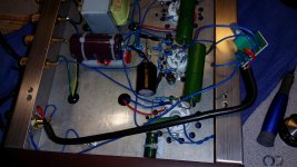
I did modifications according raindance instructions. It really sounds a lot better this way!! I use 1x6N1P and 2x6P3S russian tubes and full wave rectifier GZ32. Changed all capacitors to a better quality (Vishay, Panasonic, russian PIO). Changed volume pot to a Alps Blue Velvet RK27112. Thanks again for the good upgrade recommendations!!
I did modifications according raindance instructions. It really sounds a lot better this way!! I use 1x6N1P and 2x6P3S russian tubes and full wave rectifier GZ32. Changed all capacitors to a better quality (Vishay, Panasonic, russian PIO). Changed volume pot to a Alps Blue Velvet RK27112.
I did change my caps to PIO caps and replaced all the other caps with a panasonic caps, but that's the only the I know how to do. Can you tell me how you replaced the pots with alps, I want to do this or just replace it with a resistor but then again my knowledge is not that deep. By the way I did change all my tubes to russian tubes and the 6N1P to a 12au7.
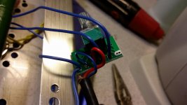
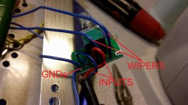
Buy Alps RK27112 100kOHM Logarithmic POT. Remove crappy stock pot, desolder R, L and GND wires from it. Take Alps POT. Align hole diameter to fit Alps POT. Put Alps POT and fasten it. Solder signal R, L and GND wires back according image:
Buy knob for the POT: 30 25mm Volume Potentiometer Rotary Pointer Knob DIY Machined Aluminum Silver 1 | eBay
And bingo!! You have good sounding, good looking POT")
Buy knob for the POT: 30 25mm Volume Potentiometer Rotary Pointer Knob DIY Machined Aluminum Silver 1 | eBay
And bingo!! You have good sounding, good looking POT
Hi cheehpogi,
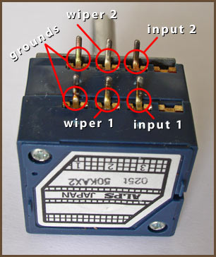
In your case pinouts are the following:
http://www.diyaudio.com/forums/attachment.php?attachmentid=512829&stc=1&d=1446709601
In your case pinouts are the following:
http://www.diyaudio.com/forums/attachment.php?attachmentid=512829&stc=1&d=1446709601
Attachments
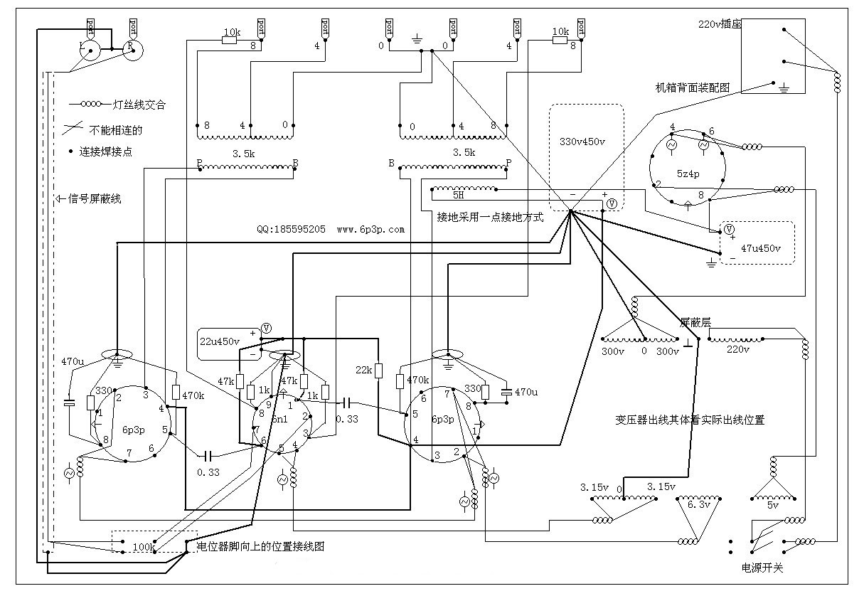
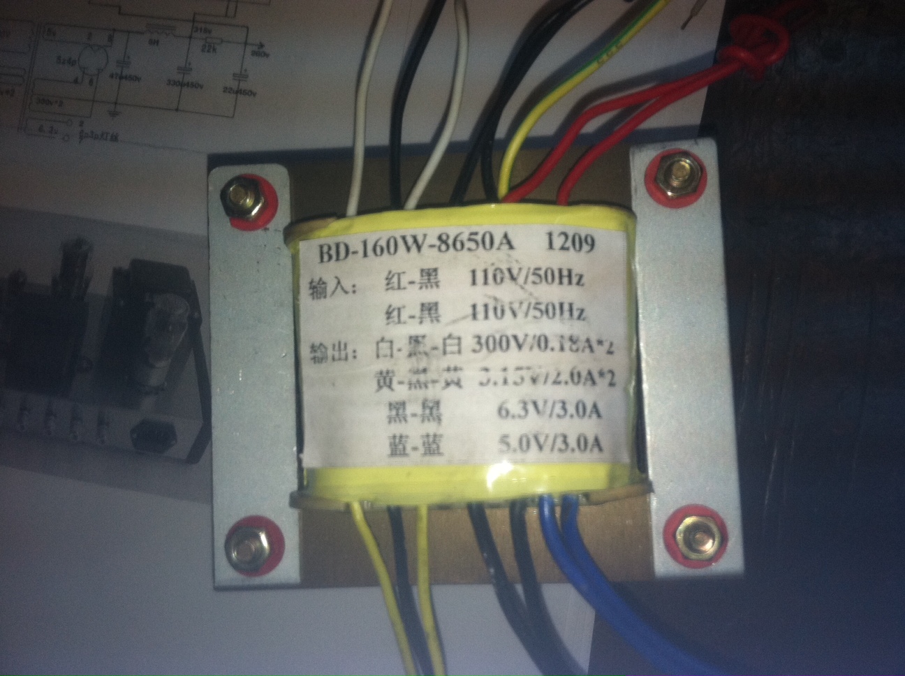
Hi I just got one of these 6P3P kits. I was wondering if I should hook up the yellow/green (center tap?) wire to the star ground. The schematic i got with the unit it looks like you possibly attach the 3.15V ground to the yellow/green center tap. (Sorry I don't have an example of that). In the wiring diagram below the 300V ground and 3.15V ground definitely go to the star ground. I have hooked up the two red wires and black wires in parallel for 110v. Thanks for any help. I have been reading this thread but have not seen an answer.

red-black: 110vAC
red-black: 110VAC
white-black-white: 300V 0.18Ax2
yellow-black-yellow: 3.15V/2.0Ax2
black-black: 6.3V/3A
blue-blue: 5V/3A
http://www.diyaudio.com/forums/atta...e-amplifier-kit-power-tranformer-6p3p-amp.jpg
red-black: 110vAC
red-black: 110VAC
white-black-white: 300V 0.18Ax2
yellow-black-yellow: 3.15V/2.0Ax2
black-black: 6.3V/3A
blue-blue: 5V/3A
http://www.diyaudio.com/forums/atta...e-amplifier-kit-power-tranformer-6p3p-amp.jpg
Hi!
Finally got this kit up and running!
Made some measurements and I have:
B+ = 375 VDC (after the choke)
Cathode voltages on the 6P3P:
left = 26.2 VDC
right = 24.6 VDC
If my calculations are right, this gives a current of 79.0mA and 74.5mA in the left and right channels, or 28W and 26W of power dissipation on those 6P3P tubes!!!
What do you suggest to adjust the amp? On turn on, the B+ goes to around 425 VDC, dropping then to the 375 VDC. I think that this initial voltage is too close to the 450V rating of the PSU capacitors.
Thanks!
Hi!
Finally got this kit up and running!
Made some measurements and I have:
B+ = 375 VDC (after the choke)
Cathode voltages on the 6P3P:
left = 26.2 VDC
right = 24.6 VDC
If my calculations are right, this gives a current of 79.0mA and 74.5mA in the left and right channels, or 28W and 26W of power dissipation on those 6P3P tubes!!!
What do you suggest to adjust the amp? On turn on, the B+ goes to around 425 VDC, dropping then to the 375 VDC. I think that this initial voltage is too close to the 450V rating of the PSU capacitors.
Thanks!
nothing out of the ordinary here...
I'm not sure I get the 12au7 idea. The circuit was not designed for it, plus the original tube type is inexpensive and more linear than a 12au7.
Regarding voltages - in the USA at least, all voltages in the amp will run high. You need a voltage converter to take your mains down to 110 volts for this kit. Of course there will be folks who disagree, but I speak the truth ��
Regarding voltages - in the USA at least, all voltages in the amp will run high. You need a voltage converter to take your mains down to 110 volts for this kit. Of course there will be folks who disagree, but I speak the truth ��
I read somewhere that the 6P3P has a maximum power dissipation of 19W, and the power dissipations in both tubes I am getting are well above that.
So I though of:
- reduce bias in the tubes to get around 13W dissipation, which means having half the current
- or reduce B+ voltage, maybe with a resistor in the transformer primary
So I though of:
- reduce bias in the tubes to get around 13W dissipation, which means having half the current
- or reduce B+ voltage, maybe with a resistor in the transformer primary
@RobFreak
They are available, I got my kit 2 weeks ago.
Is there a link?
- Status
- This old topic is closed. If you want to reopen this topic, contact a moderator using the "Report Post" button.
- Home
- More Vendors...
- Siliconray Online Electronics Store
- 6p3p tube amplifier kit