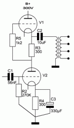
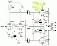
Besides the 47uF (  ) the output impedance will be around the size of the cathode resistor -correct me if I'm wrong here- which is not as low as the desired sub 10 ohm...
I'm seriously thinking about 2A3 for outputs: Ri 800 ohm, some 50mA Ia
For output voltage in 300 ohm no more than 3V is needed. Like-drive-like to cancel 2H? Hmmmmm....
I'm seriously thinking about 2A3 for outputs: Ri 800 ohm, some 50mA Ia

For output voltage in 300 ohm no more than 3V is needed. Like-drive-like to cancel 2H? Hmmmmm....

No, output impedance depends on triode used, since cathode resistor is shunted on AC by the cap. But due to non-linear Ri some rectified voltage will present between grid and cathode constantly modulating the signal by it's envelope. I do not know which tube is optimal for this arrangement since it is not an amp made for lowest distortions; rather it is like a glass ball on a Christmas Tree made to decorate it. You should ask the author, or try different tubes for yourself, but since the amp is very special you should decide which distortions do you like to generate. It is hard to tell what would you like, looking at tube's datasheets. When you go for clean sound it is easy to tell, but in this particular case it is impossible, except how well the tube fits into power dissipation requirements.
My aim for a dedicated headphones amp would be obtaining least distortion and full AF bandwidth. What I understand from Busbridge is that the use of a 20:1 OPT lowers the amp's output impedance dramatically by presenting 120Kohm load to the 12B4A, thus lowering the LF roll-off frequency.
'To get a low output impedance I needed to use quite a high step-down ratio (20:1); after all, the amplifier may be used with headphones of lower impedance than the 300 Ohms of the HD600. The output valve is the 12B4A which has a anode impedance of about 1000 Ohms, so the output impedance of the amplifier is about 2.5 Ohms, which is very low for a valve amplifier. You can use other valves here but watch that the anode impedance is not too high or the output impedance and bass-cut off frequency will both rise.
It is usual with power amplifiers to match the impedance of the loudspeaker to the impedance of the anode circuit using the equation turns ratio = square root (impedance ratio). Under these conditions, maximum power transfer takes place from the amplifier to the load. With headphones, the power involved is so small that it is not necessary to operate under such conditions. It is possible to make the turns ratio such that the output impedance of the amplifier is much smaller than the load. Power transfer is not optimum, but the output valve is tending to run under constant current conditions which has the advantage of lowering distortion.
The 2.2 K Ohms resistor on the output of the audio transformers is there to give the output valve some load if the headphones are disconnected. Without it, the transformer can ring off load. The output impedance of the amp is so low that its value is quite uncritical. '
It's not for the lust of exchanging valve types I mentioned the 6N6P, but lacking the original type. Just bought two 12B4A to try out and will report the results in a couple of days.
Got another setup running now. Impressive LF response compared to the SE from yesterday. If the driver/phase splitter looks faintly familiar, it's a straight copy from the Mullard Five Ten integrated amplifier.
Congratulations!
Got another setup running now. Impressive LF response compared to the SE from yesterday. If the driver/phase splitter looks faintly familiar, it's a straight copy from the Mullard Five Ten integrated amplifier.
Your plate resistor has only 3v across it? I must be missing something.
- Status
- This old topic is closed. If you want to reopen this topic, contact a moderator using the "Report Post" button.
- Home
- Amplifiers
- Tubes / Valves
- 6N6P Unbalanced Sound?

