since the optimum OP I observe is at very higher voltage supply (around 170V and 10mA)
You've hit the nail on the head. If the curves that I was looking at are representative then I think a minimum of 130V plate to cathode at 5mA Ip and a grid bias of -2V is needed. Add 20V for the CCS load and you arrive at 150V for the B+ requirement. Better still would be 150V p/k and 8mA. If you are stuck with the available B+ take that value and subtract from it the voltage needed by the current source to operate. If it's a simple FET they usually need only a few volts (3 or 4?) and add to that the output swing which in this case is equal to the input swing. The voltage swing of the input is limited by the grid bias voltage. If it's less than -1V then the swing is less than 2V. So figure 6-8V for the CCS load. You can see here one of the advantages of a CCS load. It consumes less voltage than a resistor load freeing the voltage up for the tube. Now you have a value for plate voltage. Plot it on the set of plate curves and pick a plate current that gives you a decent (as best you can) grid bias voltage. Remember that for a CCS load the load line is horizontal. I suspect the plate current will be on the low side so don't expect this circuit to be able to drive much capacitance.
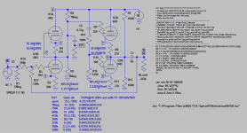
Hi, I would like to share the sim of mod with you all. The sim is done 3 times with HT 30/60/90V to gather THD% results. It appears that THD is reduced as HT goes up straight then tapper off. The input impedance is about 100K with R17 120K output impedance ~2K with larger output cap (25uf?) for 10K load and good bottom response. If you like more plots let me know.
Attachments
Last edited:

Hi Koonw.
Your approach is very desirable but for this post instead:
http://www.diyaudio.com/forums/tubes-valves/276129-4x6n3-preamp-board-ebay-2.html#post4563450
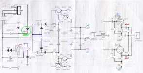
The schematic is here:

If you can help a bit with this SRPP, with distortion plots and variable gain for 6n3/GL-5670 it'll be awesome...
The original Aikido have R1-R2 with 560 Ohms and R3-R4 with 200 Ohms, from what I saw in the pictures. Gain is around 10X (20db).
Here are the results:
R17 Gain db THD%@1V RMS out with HT 30V/60V/90V
open ~23-24 (15X) 0.53/0.063/0.095
1Meg 15.2 (5X) 0.22/0.026/0.039
750k 13.6 (4.4X) 0.2/0.022/0.033
680k 12.9 (4X) 0.18/0.021/0.032
470k 10.6 (3.3X) 0.16/0.018/0.026
390k 9(.3 (2.7X) 0.13/0.015/0.023
270k 6.7 (2X) 0.11/0.012/0.019
180k 3.6 (1.4X) 0.089/0.0096/0.061
120K 0 (1X) 0.076/0.0078/0.012
Edit: 60V is way to go for lowest THD according to the sim
Attachments
Last edited:
I realize I'm resurrecting an old thread, but I'm using this same tube buffer for my TPA3116 amp and while testing I noticed the heatsink on the 7805 is really hot - as in, I can't touch it after a while.
(Used setup: tube replaced with Russian 6n3p-ev, power supply 12v ac wallwart)
In this thread I read that using a 7806 instead of the standard 7805 would better match the filament specs - and as far as I've been able to deduce dropping to 6v instead of 5v would reduce heat also?
So my question is - would it be sensible to replace the 7805 with a 7806, and if so, any recommendations on a specific part to get?
Sorry if these are stupid questions, I'm a complete noob in electronics but I'm trying to learn along the way..
Last edited:
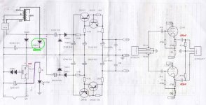
That's what I did and it worked for me. Also bolted a small heat sink onto the regulator and upgraded the caps. Been a long while, but I think I made a few other minor changes as well. Have a look at the schematic for ideas. As I recall I had quite a bit of fun with this project, tried some other tubes and so on...
I built a tube preamp into an SX 780 receiver which allowed the use of the panel light 7.5 volt winding with 3.3 ohm resistor for the heaters and the VAS stage supply to voltage triple the B+ to 155v. then using a 2N5551 to provide a noiseless 133v to the 6922 circuit.
Best upgrade yet.
Best upgrade yet.
That's what I did and it worked for me. Also bolted a small heat sink onto the regulator and upgraded the caps. Been a long while, but I think I made a few other minor changes as well. Have a look at the schematic for ideas. As I recall I had quite a bit of fun with this project, tried some other tubes and so on...
I replaced the caps with some Nichicon Muse caps I had laying around, but they're specced to 85 degrees. Which made me worry about the heat generated by the 7805
Which 7806 did you use?
CAN YOU PLEASE WROTE YOUR MODIFICATIONS ON THE ORIGINAL SCHEMATIC AND UPLOAD TO BE ABLE TO MAKE A EXACT COPY OF YOUR DESING? IT WILL BE GREAT FOR ME!!!
Hi People.
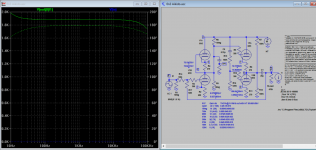
Finally I finish the prototype tests for the "Phase 2" and "Phase 3" of 6N3 buffer.
Phase 2 consists in a CCS implementation with 2SK30A FET or a dedicated CCS diode.
Phase 2 already with a higher plate voltage PSU transformer. The Heater power line is separate now with a dedicated secondary voltage.

Phase 3 with the same CCS theme based on the 2SK30A.
About 3.8mA cathode current rise the HD to high.
Now the new voltage regulators circuit are implemented and working well with a higher plate voltage, around 85,5V, and a good"Buffer input voltage" for the regulators do their job "well".
Smoother sound is noticed at the "start-up" of this toy.

Final Phase 3 implementation.
Diode CCS is preferred since HD is around -50db (0,32%) at 3,5V RMS input (9.9V PP) 20Hz to 20kHz.A much lower HD value than obtained with the 2SK30 CCS; but its a matter of current since the FETs drain about 3,8mA and the diodes are configured to deliver a smaller current. The PCB space is small so this solution is "better".

Signal attenuation is very low, around -0,4db, stereo separation is about 40db at 20kHz and frequency response is flat from 10Hz to 100kHZ.

Poor specs for digital age but the sound is very gutsy...
...so I don´t give a "bit" about the poor HD and stereo separation.
For 2V RMS digital output HD is even better, and the output holds a 10kOhms load.
The tube is a 6N3 with a "M" grade mark. A "J" military grade is even better, specially at HD values. The GL-5670 works also very well or even better than the "J" grade 6n3.
Cheers

 Please don't post all caps, it's a violation of forum rules. Thanks!
 CAN YOU PLEASE WROTE YOUR MODIFICATIONS ON THE ORIGINAL SCHEMATIC AND UPLOAD TO BE ABLE TO MAKE A EXACT COPY OF YOUR DESING? IT WILL BE GREAT FOR ME!!!
OK, sorry for my caps... cab you please..?
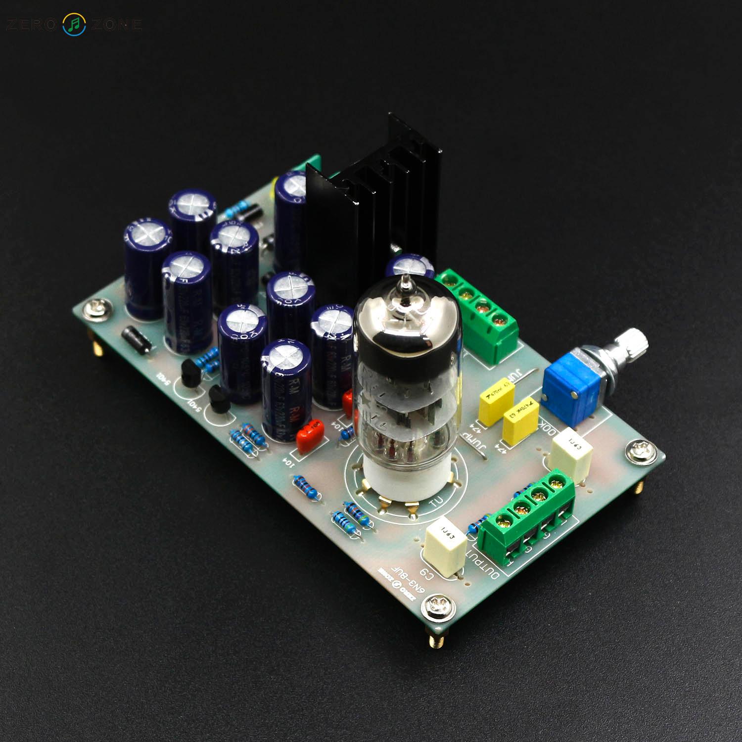
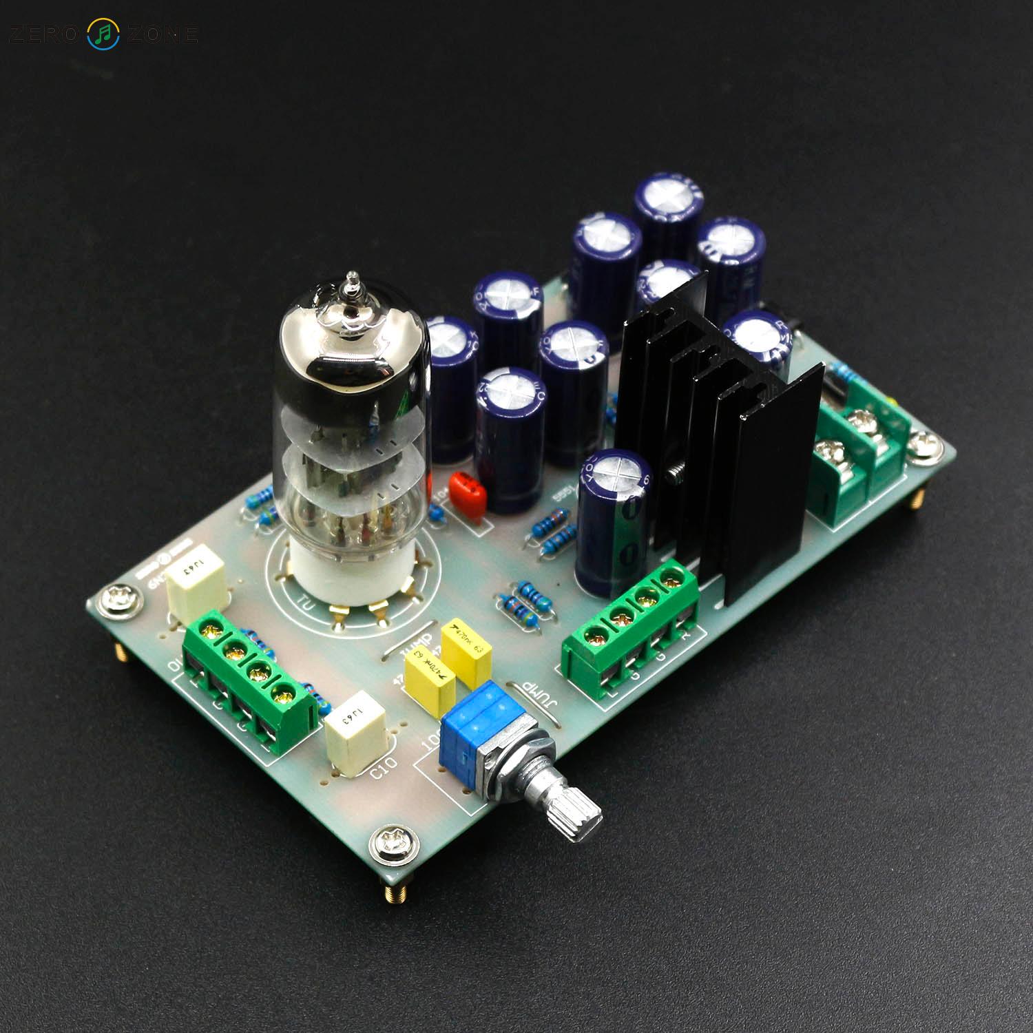
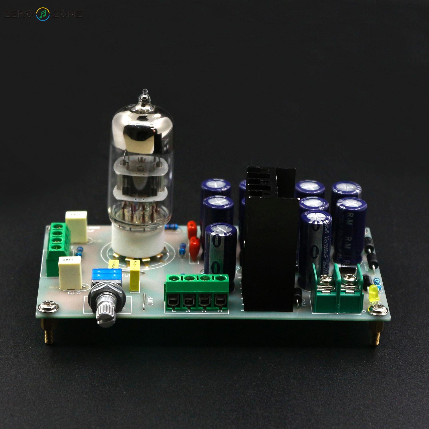
Has anyone tried the Zerozone version which claims to have fixed the voltage issues? I noticed that some of the caps are 63V suggesting they have boosted the voltages from the first design on this thread many years ago. PCB looks single sided - rubbish?
An externally hosted image should be here but it was not working when we last tested it.
An externally hosted image should be here but it was not working when we last tested it.
An externally hosted image should be here but it was not working when we last tested it.
Last edited:
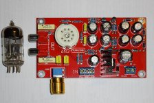
I also have a 6N3 board laying around (see photos), waiting for some time to be married to a 41Hz Amp6 and a USB DAC to make a nice PC amp.
"Ah!buis", our local (dutch dyi audio forum) tube guru came with 2 simple modifications to improve the performance. The first is to use a 12-0-12 transformer, the second will increase the voltage on the tube to 48V (will require cap upgrade as well)
I have not tested it, but with my new reading glasses I should be able to see the print well enough to do the soldering I hope te find some more spare time at the end of the year to actually continue with this project
"Ah!buis", our local (dutch dyi audio forum) tube guru came with 2 simple modifications to improve the performance. The first is to use a 12-0-12 transformer, the second will increase the voltage on the tube to 48V (will require cap upgrade as well)
I have not tested it, but with my new reading glasses I should be able to see the print well enough to do the soldering
I hope te find some more spare time at the end of the year to actually continue with this projectAttachments

12VAC is about 17V peak. There are 2 voltage doublers (a + and a -) with the diode drops There should be about +33V and -33V, and there are 2 voltage regulators that give about +30V and -30V out. The triodes are wired as cathode followers, so the gain is less than Unity (less than 1). The voltage across the triodes are [60V - (the drop in the self bias resistor + the drop in the cathode load resistor)].
Oops, I just saw that this was not a new posting, just a new comment on one that already has over 130 posts.
Oops, I just saw that this was not a new posting, just a new comment on one that already has over 130 posts.
Last edited:
I also have a 6N3 board laying around (see photos), waiting for some time to be married to a 41Hz Amp6 and a USB DAC to make a nice PC amp.
"Ah!buis", our local (dutch dyi audio forum) tube guru came with 2 simple modifications to improve the performance. The first is to use a 12-0-12 transformer, the second will increase the voltage on the tube to 48V (will require cap upgrade as well)
I have not tested it, but with my new reading glasses I should be able to see the print well enough to do the soldering
I'm at that need-stronger-glasses time of life too
Thanks for posting the pics. I've ordered two of these out of curiosity (apparently channel separation is poor so each one will be mono). AFAICS the only difference on the ones I'm getting is that the 1n4007 diodes are now FR207 fast recovery types. The rest seems to be the same. I'll post pics when they arrive.
- Home
- Amplifiers
- Tubes / Valves
- 6N3 Tube Preamp with DC-DC converter